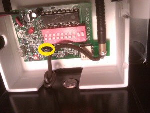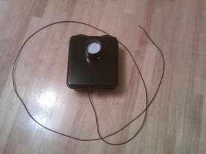
This is a photo of the radio transmitter inside of a Dakota Alert WMT-3000 wireless driveway alarm system. The wire coming through the hole drilled in the bottom of the case and soldered to the base of the antenna extends out to a 27″ wire whip antenna. Note the jumper circled in yellow. This jumper has a “high” and “low” setting. It is set to the “low” setting by the factory, and the “high” pin has been cut off. I found that the range was extended by soldering the “high” (cut off) pin to the center pin.

Thanks for this post!!!! one question…. why did you choose 27″ for the antenna? UHF resonance or just what you had for length? Would low loss RG8 increase the range with an NMO mount UHF antenna? Im thinking the transmit power is so low that the power would be dissipated before it got to the 1/4 wave antenna
Yes, 27″ is about 1 wavelength. Not being an antenna design engineer, I have no idea how that works out in practice, other than to say that it did extend the range far enough for the application.
How did you come up with that? The wavelength of 433.92MHZ is about 0.69137 meters, a quarter of that (1/4 Wave) would be about 17.3 CM, and you can’t just run 2 antennas without very complicated math and have it work right. To do it correctly you need to remove the original antenna and run a section of coax with the shield grounded to the RF ground to your 1/4 wave antenna. The 17.3CM length starts after the shielded section. I use brass rod for rigidity and corrosion resistance. What you suggest in your article is very mis-matched, and would tend to bleed RF around the spectrum. As for the HI-Low jumper, it most likely runs above a power level allowed in the US by the FCC in the HI position, thus the reason for the pin being cut off. If you run too much power and cause interference, you are subject to fines.
You are right, 27″ is 1 wavelength, not 1/4, My earlier comment was incorrect.
Thanks for this. I am a little confused as to how both the shield and center conductor should be connected to the Dakota transmitter board on the coax application you mention above. There just seems to be a single conductor / lead that runs to the factory antenna mount. Also can the system range be improved by making the same mods to the reciever?
Thanks again.
Don
The center conductor would be connected to the antenna signal. The outer shield would be connected to ground (the negative side of the battery if nothing else presents itself on the circuit board).
Jay, I am curious why they would cut the HIGH pin? Any thoughts? If you solder the HIGH pin, does that mean you remove the connection to the LOW pin setting?
Please advise.
Thank you. Good work!
Lawrence
I don’t know, but it could be that they sell a more expensive model that has longer range, but use the same circuit board in both models and wanted to disable the “extended range” option from the low end model.
Yes, you should only connect one of the two pins (high or low, but not both.)
Great article! There was a technical issue with the 3000 transmitter operating at the 3000′ range that it does operate at with the FCC. Cutting the pin was the “solution” to make the boards compliant. The Dakota 2500 products use a different style of transmitter and come with a 2500 foot range out of the box (so no soldering required).