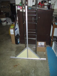
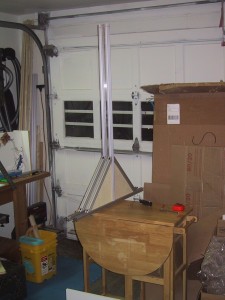
Here is the final frame (without covers except for the triangular end pieces):
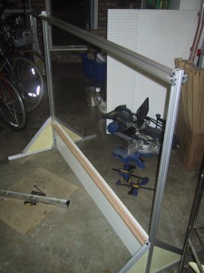
I cut the extruded aluminum t-channel pieces to the correct size and assembled them with the MDF tube support and plywood end panels (not yet stained/finished).
Here is a picture of one side panel, plus a “one tube, one inch wide” bubble display that I mocked up before getting the tube support finished:
The two end panels are connected at the bottom by the tube support, which is just a MDF shelf on it’s side cut to the correct length. This piece of MDF rests on the ground along its entire length and serves as the support for the tube holder. I used a carpenters square and a level to make sure the tube support (and end panels) were square and correctly upright while attaching it. I would attach one bolt, and then square everything up before attaching the other bolt.
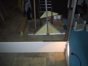
The tube support is screwed to the tube holder MDF using 32 wood screws. I might have been able to get away with 16…but I know 32 will hold!
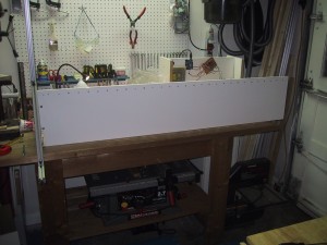
As pictured here, the frame without electronics, tubes, motors or front/back covers weights in at 30.2 pounds.
Next up: Drilling 60 holes to mount the motors, and 30 or 60 holes for the motor power wires (I may combine the wires from two motors into the same hole, I haven’t decided yet) … and soldering connectors onto 60 motors (Which goes at around 20 motors per hour….).
