Part 1 told how to make your computer output commands to the 3 stepper motors controlling the X,Y,Z axes of the mill so that you could jog them around under computer control.
This post deals with getting input from the switches on the mill to your computer.
I am interested in getting input from 4 switches on the mill. First, the Emergency Stop button on the front panel is great to have operational!

Second, I want to be able to use the three Home switches to home the axes, as well as act as limit switches.
(The mill does not have limit switches on the other side of the axes, so you will have to configure you software to use “soft limits” with respect to the home position of the mill.)
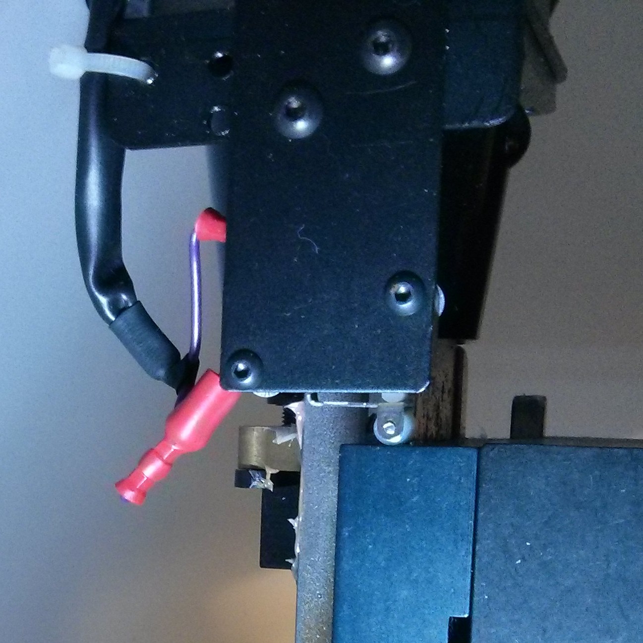
These switches are connected to ground, but when they are activated, they open, which will allow the control line to (potentially) raise to 5V (active) assuming you have it configured with a “pull-up” resistor to 5 volts. My break out board had a jumper that I just moved from “pull-down” to “pull-up” to automaticlly apply a pull-up resistor to these lines.
Get the E-stop working first in hardware and software. Always nice to be able to push it when your mill is driving an axis through a home switch due to a software misconfiguration or wiring mistake. [FYI – once you hit the big red button, you have to rotate it clockwise to get it to ‘un-pop”.]
See Part 1 for a description of the B,C,A, 1-32 coordinates of the 96 way connector. We will be adding 4 wires for the X,Y,Z home switches and E-Stop.
A25 - (E-)STOP. [red wire] to Parallel pin 13.
(I believe this line (only) has a pull-up on the Baldor board
as it moves to 5v when pushed even without a pull-up resistor configured. But having another pull-up on the break out board for it did not seam to hurt.)
The three home switches are wired as follows:
C26 - Home 0 (X axis). [blue wire]  Parallel pin 10

B24 - Home 1 (Y axis). [green wire] Parallel pin 11

C23 - Home 2 (Z axis). [white wire] Parallel pin 12
NOTE: The X axis home switch is on the “reverse” side (max coordinate, not zero coordinate), so you will have to set your software to do a “reverse home” on the X axis, otherwise it will just try to home the table all the way to the right and never hit the home switch.
My DIN connector from Part 1 has been updated with 4 more wires down on rows 23-26 and now looks like this:

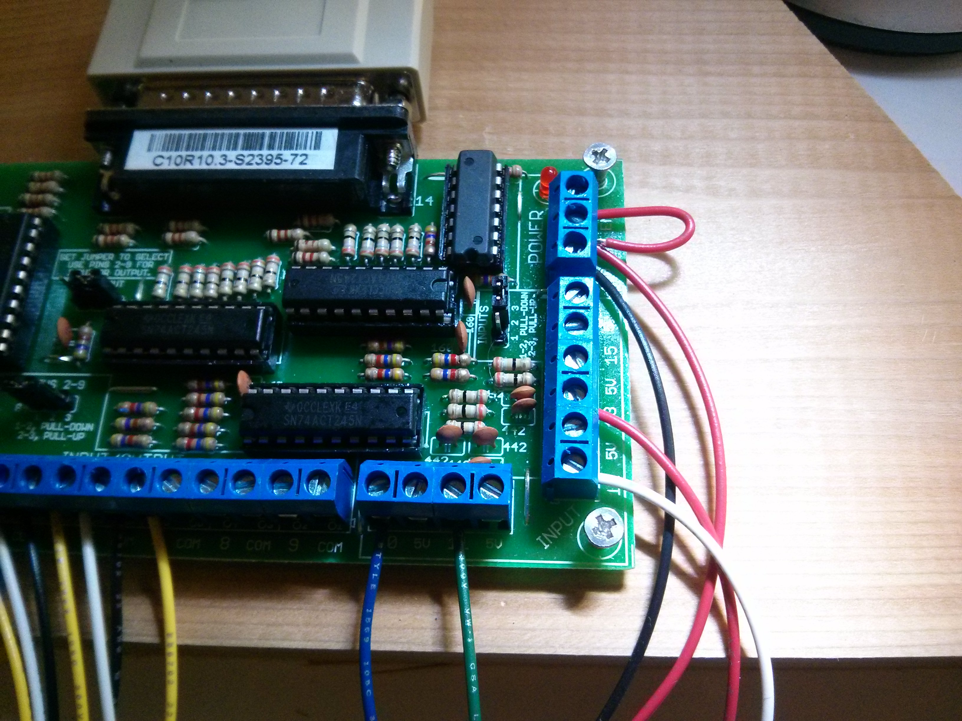
And the breakout board is now using pins 10-13 on the right side:
Now that we have those wired up, the only thing remaining is the spindle motor control (and possible RPM sensing). Part 3 of this series shows how to turn the spindle on and off using an output pin on the breakout board. It also has an embedded video showing the limit switches and E-Stop in operation.
Pingback: How to convert a Denford / ScanTek 2000 Micromill to LinuxCNC / Mach3 control: Part 1 – 3 Axis control | Jay's Technical Talk
I was wondering if you ever figured out how to wire the spindle? If so, could you post instructions on that?
Thanks!
Yes, see part 3 that I just added here:
https://www.summet.com/blog/2016/01/21/how-to-convert-a-denford-scantek-2000-micromill-to-linuxcnc-mach3-control-part-3-spindle-motor-control/
Pingback: How to convert a Denford / ScanTek 2000 Micromill to LinuxCNC / Mach3 control: Part 4 — Spindle Speed Control | Jay's Technical Talk
Hi Jay,
First off I’d like to thank you for all your efforts with this blog and helping me get the micromill off the ground. I am truly appreciative.
Now on to business I’m hoping you would be willing to help me once more in figuring out why I don’t have any inputs. I cannot get the e-stop or limit switches to work? I have them wired accordingly. i.e. E-stop wired from pin A25 on the 96 pin to pin 13 on the BOB etc. I also have the pullup resister on the BOB set to pins [2,3] (pull up).
In mach3>configure>input signals I have EStop Enabled,set to Port 1, Pin 13. but nothing happens when pressed. Limit switches have no effect either.
Was there something else that you had to enable or configure in mach3 in order for the inputs to work ?
Thanks again,
Doug
I’d suggest that you go into the diagnostic area on Mach3 where it shows you small “lights” showing you the pin states, and connect a wire from ground to pin 13 on your breakout board (and then disconnect it) and make sure that the light toggles colors (red/green).
You may need to “invert” that input, depending upon how things are set up in your software.