The Icom IC-725 radio has three optional expansion units that may or may not be installed.
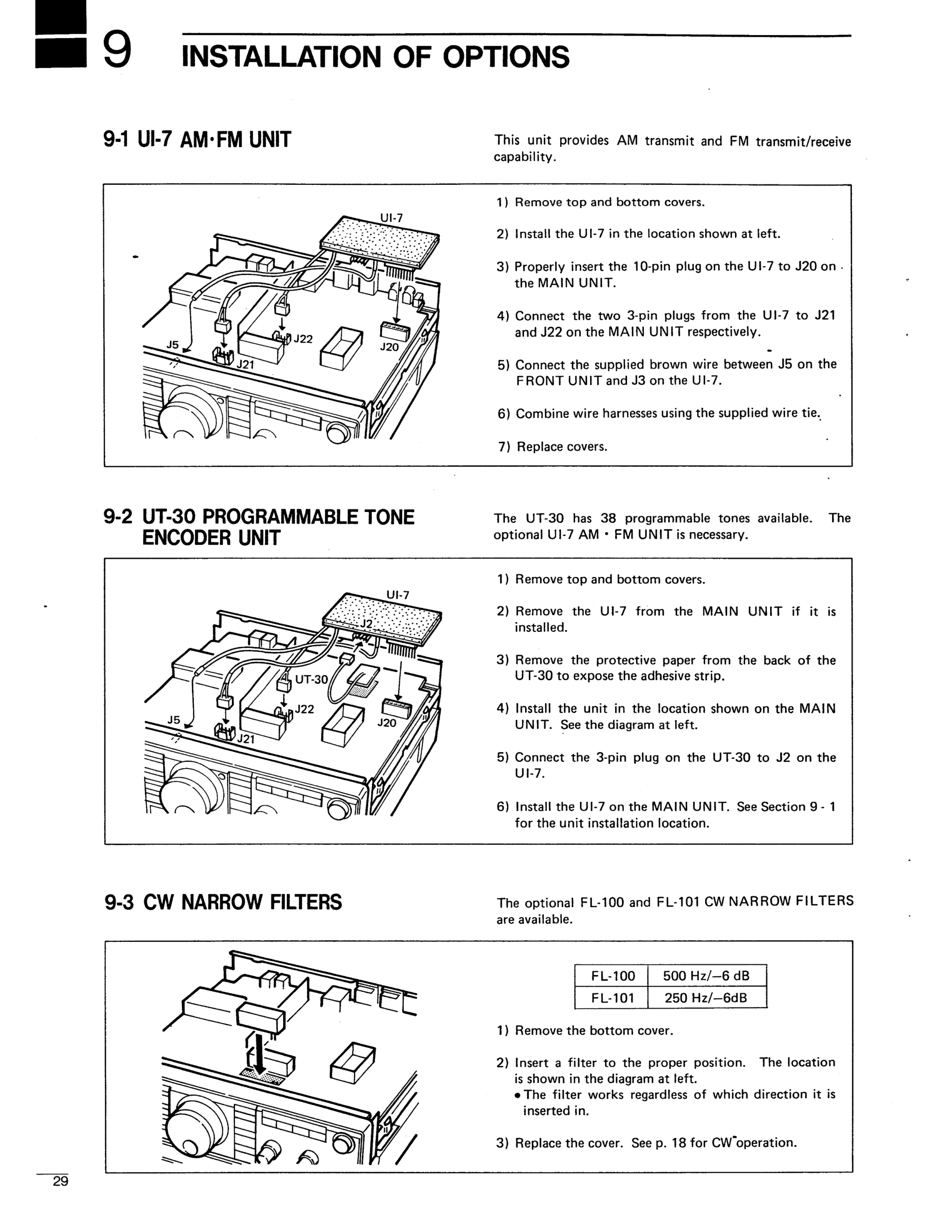
The UI-7 AM/FM Unit allows it to operate in AM and FM modes (in addition to SSB and CW) and plugs into the bottom of the main circuit board near the rear of the unit. When it is installed, the air flow grill openings on the rear right side of the bottom of the radio will be blocked. (Looking at the radio upside down from the front/knob side)
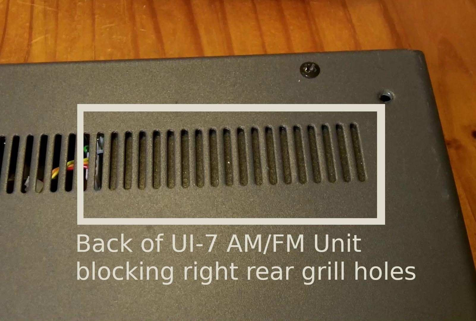
(Empty) Location where the UI-7 AM/FM unit would be installed (also the UT-30 tone unit would go under it.
[All IC-725 radios have the FM/AM and CW/Narrow buttons on the front panel, so the existence of these buttons, or even the AM/FM icons lighting up on the LCD panel doesn’t mean anything.]
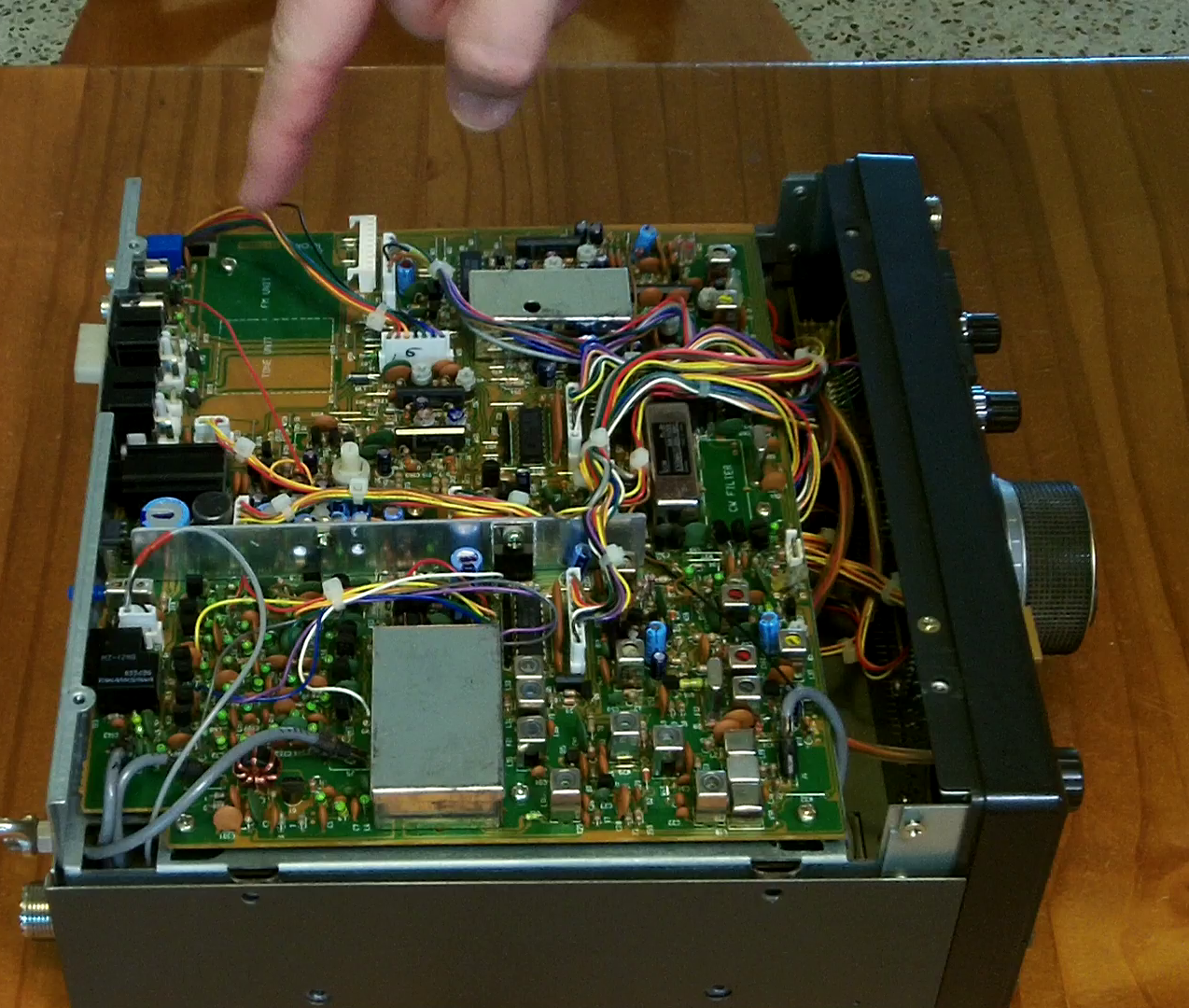
The FL-100 or FL-101 (500Hz or 250Hz) Narrow CW Filter units plug into the front middle of the bottom main board. You can faintly see a rectangle in white with the text “CW Filter” inside it on the green circuit board to the left of a silver crystal if the optional CW narrow filter is not installed. [If it IS installed, it will look like a larger rectangular prism that covers the “CW Filter” writing, usually silver in color with a black sticker on top.]
![]()
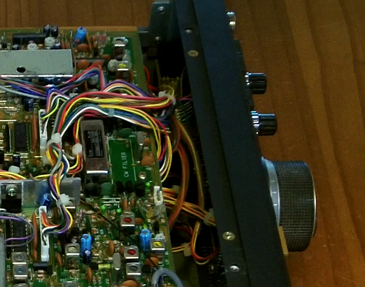
Empty location for the narrow CW filter outlined in white with “CW FILTER” on the main circuit board
The UT-30 Programmable Tone Generation unit plugs into the UI-7 unit but is invisible from the outside of the radio as it is sandwiched between the main board and the UI-7 board when installed.


")