My forward power meter was not moving at all, and it later turned out that the reverse meter wasn’t moving correctly. The root cause was that both of the diodes in the meter circuit had blown (Not sure why, perhaps somebody put a LOT of watts through the unit? Apparently this is a common cause of problems for the meters on MFJ tuners from this era).
The final solution was to replace both diodes (the forward diode had failed open, and the reverse diode had failed “closed” but not working as a diode properly so some forward current was going through it to mess up the reflected power reading).
These 1N34A Germanium diodes appear to work as well as the OEM diodes, even though they are not the blue/black color scheme and are physically smaller.
I didn’t want to unsolder all of the PL259 coax jacks and take the front cover & knobs off just to get access to the trace side of the circuit board, so I instead soldered the new diodes to the legs of the old diodes (so the old diode body would keep the legs from falling down if the solder on the traces below melted) and then clipped out the old diodes. Not as clean as if I had access to the bottom of the circuit board, but a lot faster and much less likely to break the set screw threading of the 30+ year old plastic knobs.
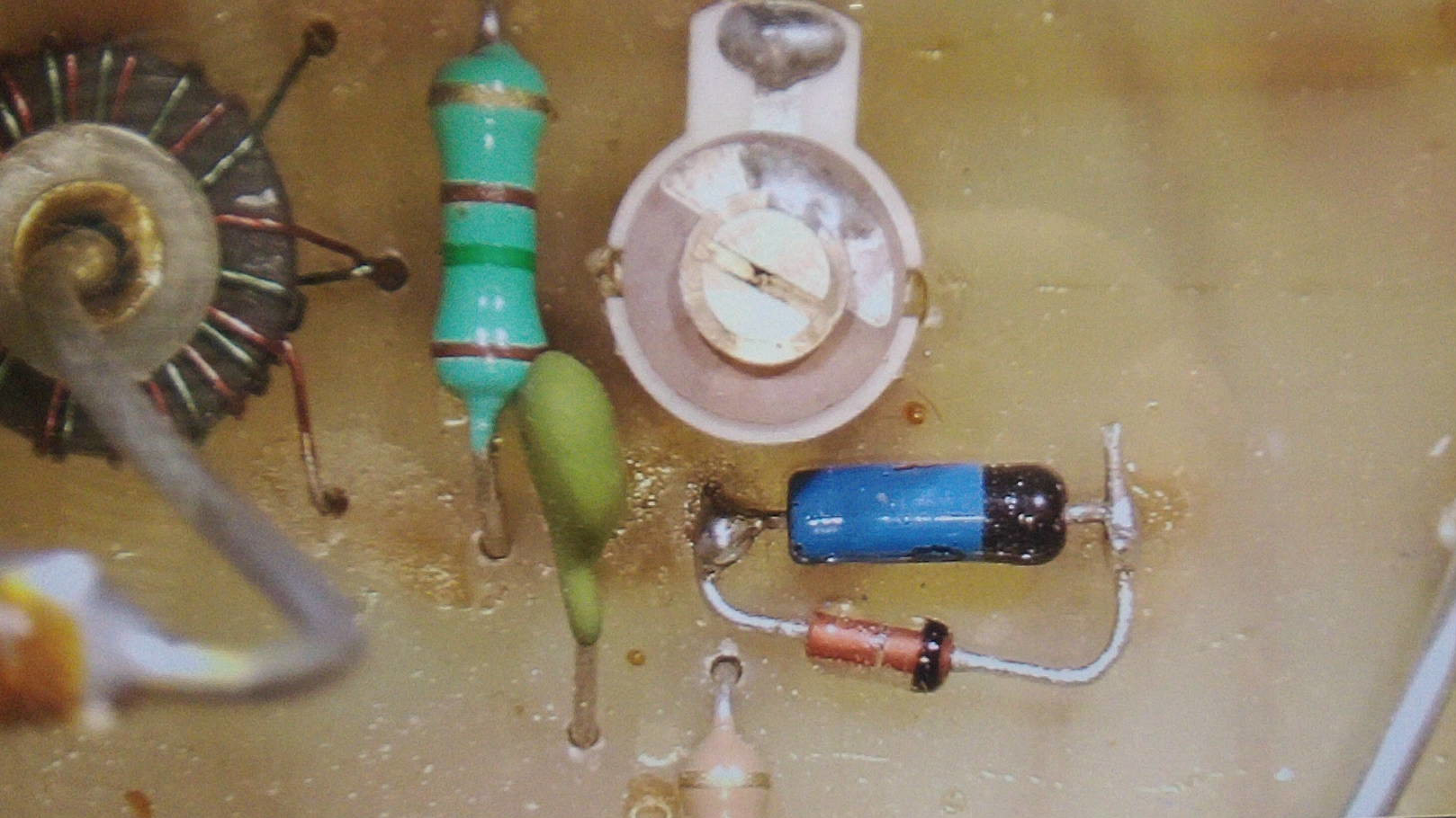
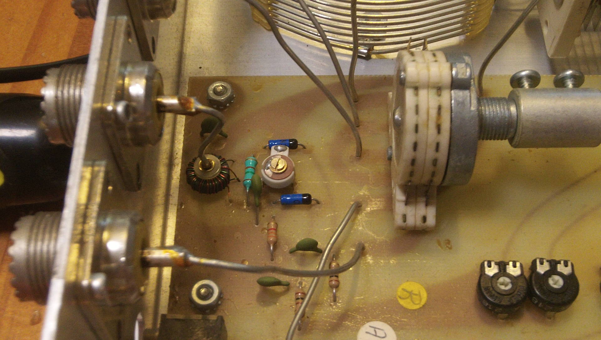
In the above image you can see one of the new diodes bypassing the old diode (before I cut away the original shorted diode). You can also see the “balance” tuning capacitor just above it, and the current sensing transformer with the transmitter feed-line going through the center at the far left.
After I replaced the diodes, I calibrated the meter by adjusting the Hi/Lo power pots for both meters, and I also had to adjust the small tuning capacitor located between the diodes. [As far as I can tell, this guy adjusts the “balance” between the forward and reverse circuits, possibly to adjust for diodes that are not perfectly matched?] I had to measure the effect of adjusting the tuning capacitor with the case on, as it changes behavior with the lid off, so there was a lot of setting the lid down, checking, lifting it up and turning slightly, setting it down again, etc…
The level potentiometers I was able to adjust with the lid off just fine using a plastic screwdriver so I could just set a power level on my radio, feed it through the tuner to a dummy load, and twist the pot until the needle matched my reference meter.
I could tune high (1-60 watts) reverse power meter just by reversing the coax connectors my radio and the dummy load were on (reversing the path of the power). But since my radio only goes down to 10 watts at the lowest setting, to tune the low power setting (1-30 watts) I hooked it up to an antenna and transmitted on a band that wasn’t great for the antenna to get a controllable 1-10 watts of output power (which my radio can handle for a short period of time).
Amazon Affiliate Link:


