I have opened my 2013 Nissan Leaf battery pack and removed the modules. The tools needed are:
- 500 volt class 0 (or better) electrically insulated gloves
- One or two full rolls of black electrical tape, for covering your tools and the terminals of the modules when you remove them.
- Regular leather gloves
- Side clippers and needle nose pliers for removing wire tiedowns
- 1-1/2″ putty knife or chisel and hammer. (or preferably an air chisel)
- 10 mm wrench (preferably a socket with ratchet)
- 13 mm deep socket
- 16 mm wrench and hammer (or impact driver w/ 16mm socket)
- small flat bladed screwdriver for prying clips
- # 1 Phillips screwdriver for removing screws on the sense terminal of the modules
You can watch the 13 minute youtube video here, or spend about the same amount of time wading through my wall of text below….
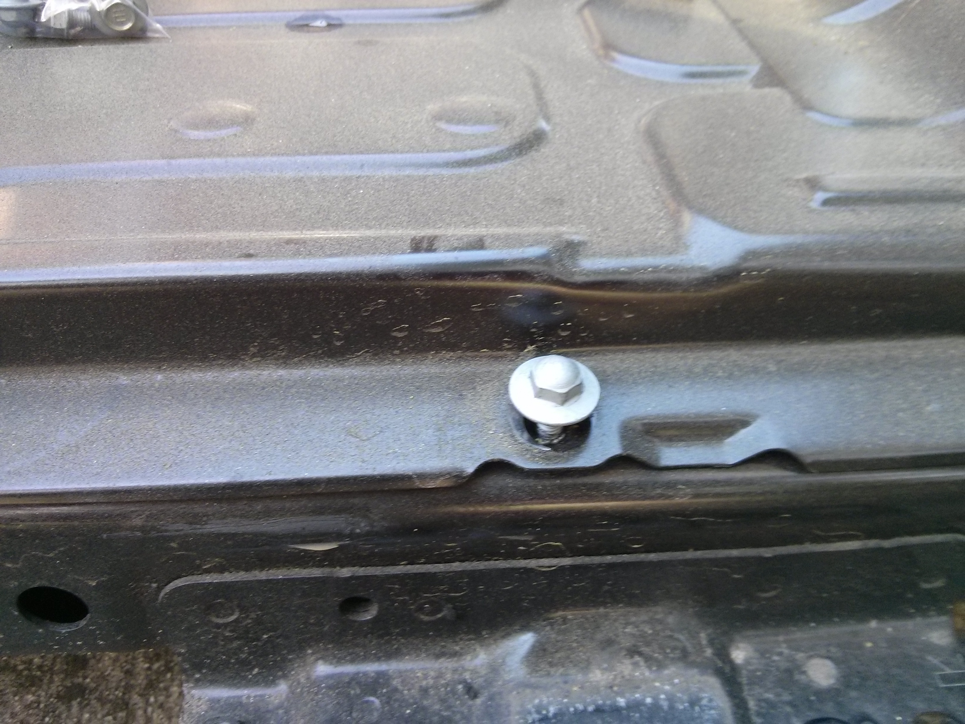
First: Remove the twelve 10mm bolts on the edges of the battery, and the six 10mm bolts from around the service disconnect, and remove the aluminum plate from around the service disconnect.
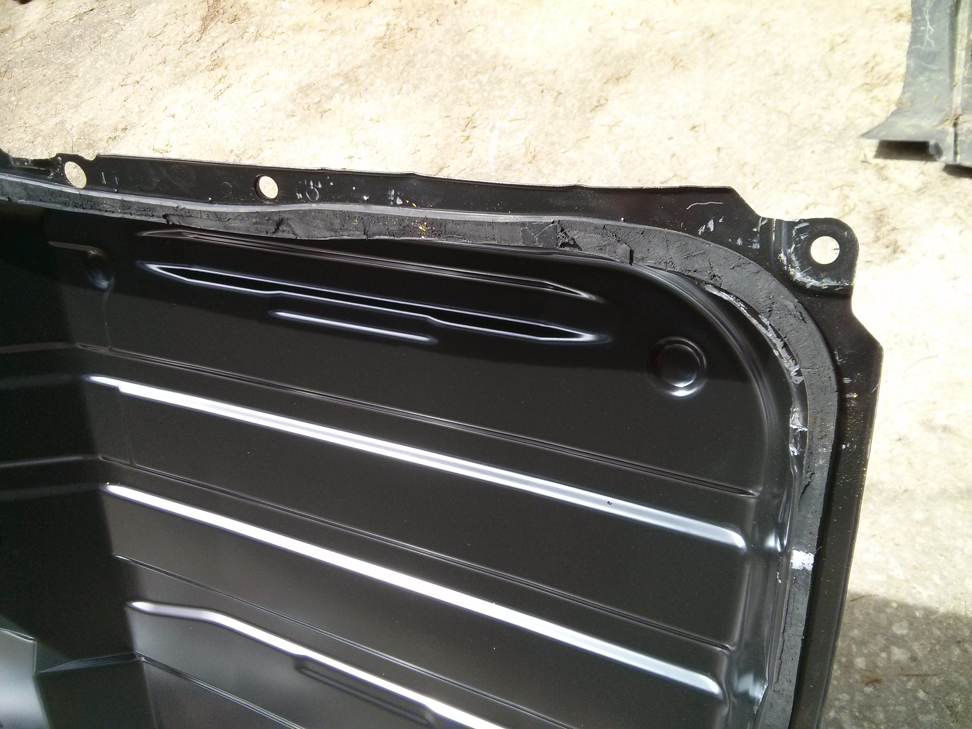
Second: Using a putty knife or chisel, cut the waterproof seal that is holding the battery cover onto the shell. If you don’t mind bending the steel, you only need to do 3 sides, but if you want to preserve the steel of the cover and shell, you’ll need to do all four sides. An air chisel is highly recommended, as it will take you several hours if you do it by hand (like me). The lid fits down over a lip that is at least an inch high, so you can just hammer through the seal material until your chisel hits metal without having to worry about piercing a lithium cell. The photo below shows the seal on the inside of the cover after it was lifted up.
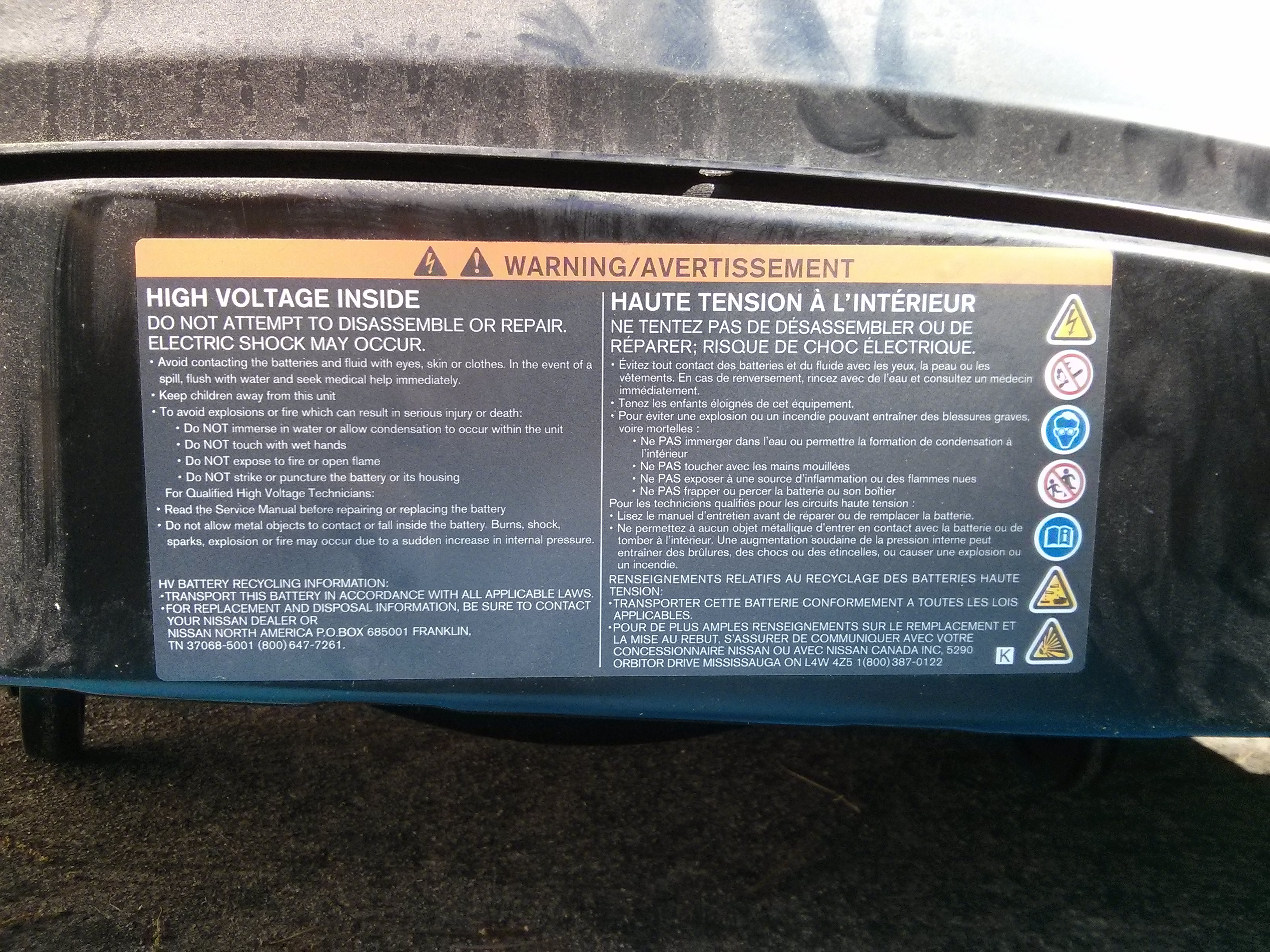
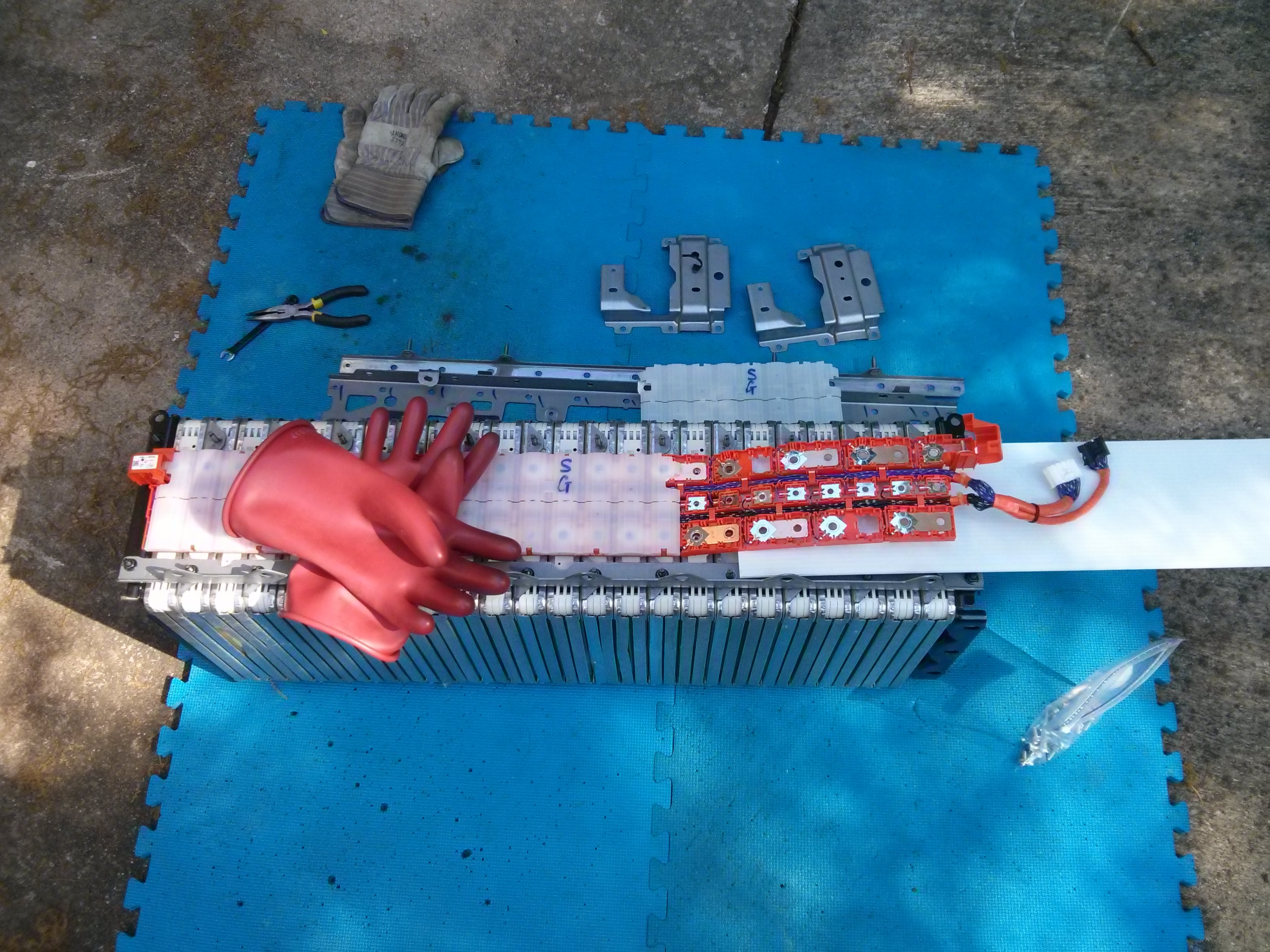
Third: Put on your high voltage gloves! There is a lot of high voltage in there, even with the service disconnect removed (you DID remove the service disconnect, right?). If you haven’t already, re-read the warning sticker on the back of the battery.
Fourth: If you decide to risk your life working with high voltage packs of batteries, do it safely. Use electrically insulated wrenches, or cover as much of your wrenches as possible with electrical tape so that if you drop a wrench across a set of terminals, it may not weld itself to them, shorting out a good sized chunk of your battery and causing it to burst into flames or balls of plasma.
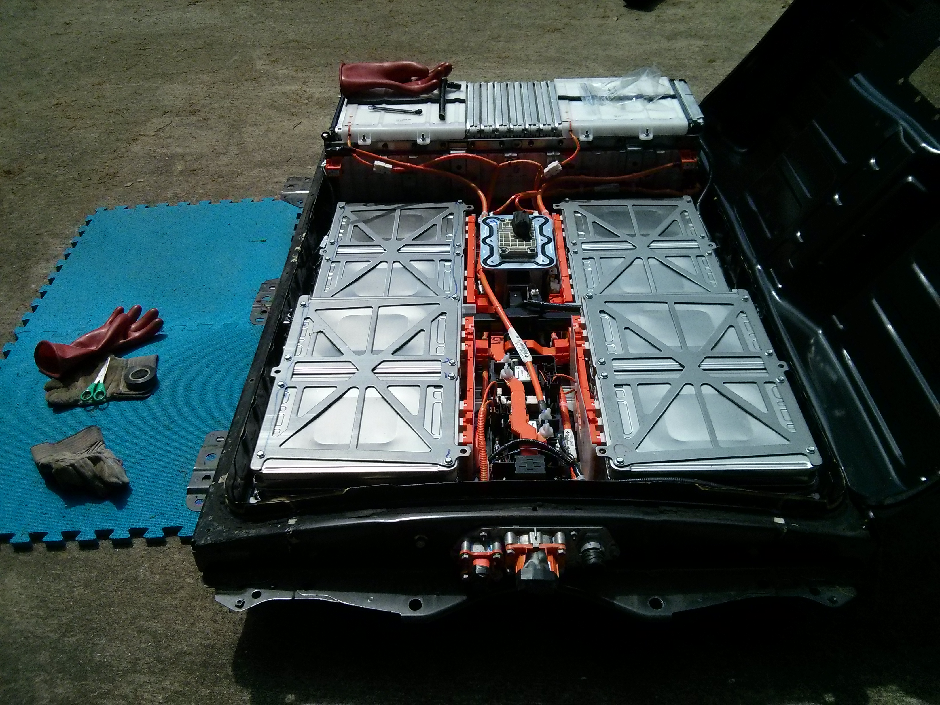
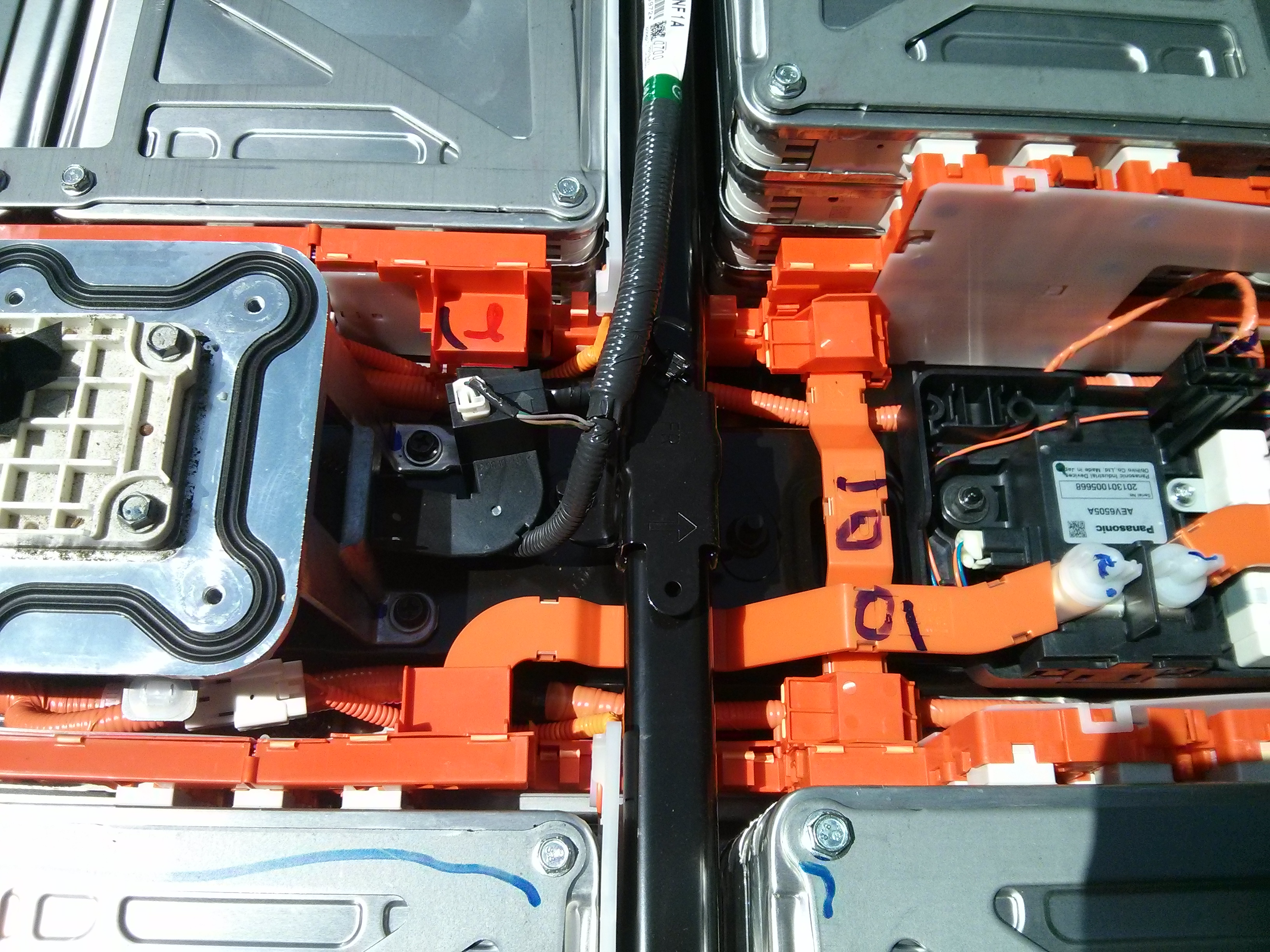
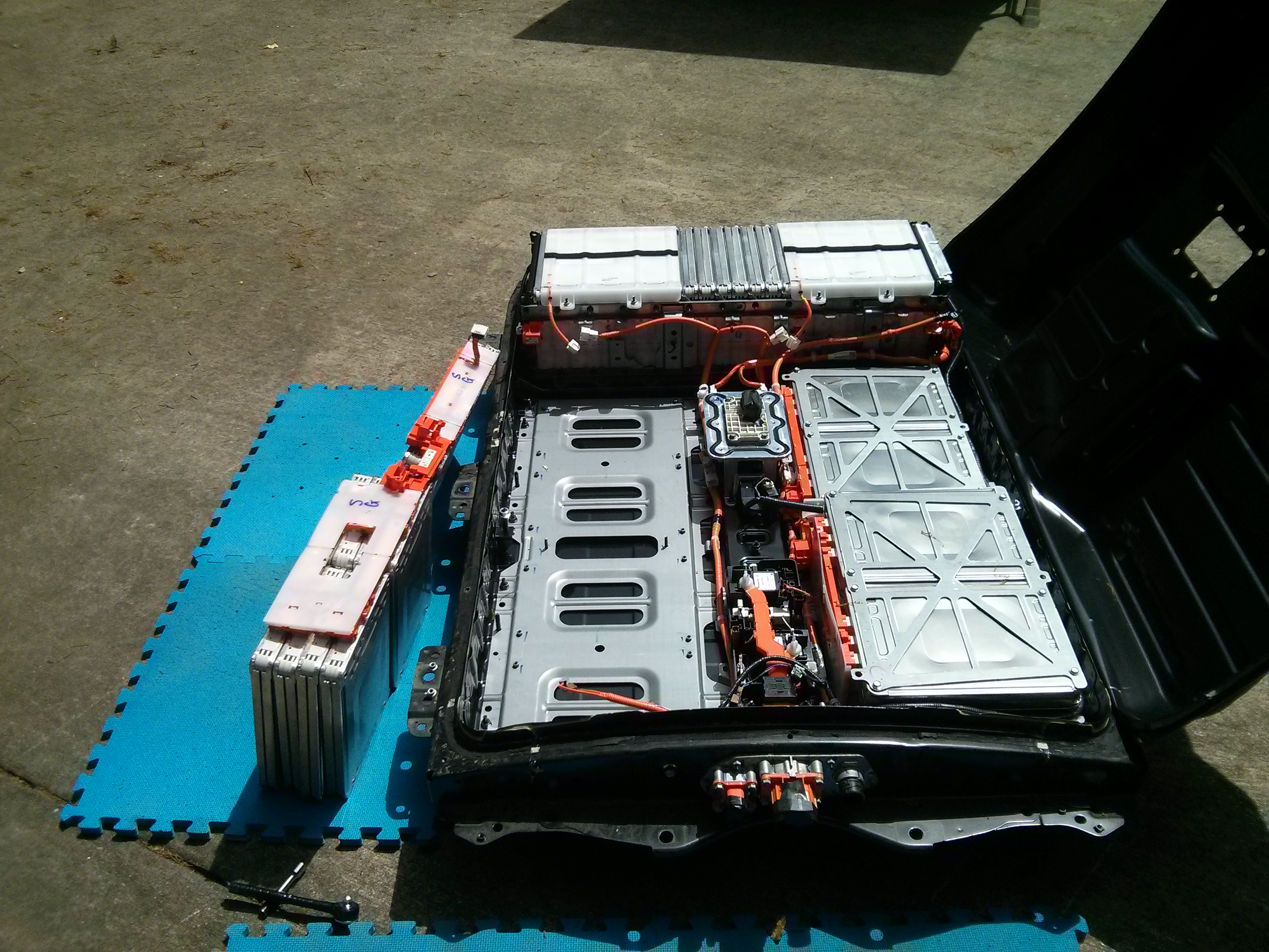
Separate the full pack into smaller sub-packs so that the voltage differential is smaller by removing the orange cables. The first two cables I removed were the ones going to the ends of the row of 24 modules in the back of the battery. I covered the ends of the cables with electrical tape as I removed them. Then I removed the two bus bars that were marked “01” (or “10”) from the factory, shown in the picture below. There was enough room to remove the short one from under the long one, and then remove the long one from under the black steel bar without having to remove the black steel bar (yet). Note that the plastic insulation is ONLY on the top of the bus-bar, and the bottom is bare copper, so don’t touch without your insulated gloves!
Fifth: Disconnect all of the random small plugs and wires, including the black thermocouple probes, the HV wires that go to the cabin heater port, the several plugs for the BMS wires, and the orange wires that go to the tin panels around the batteries. The tin panels are battery heater elements that turn on in cold weather to maintain a safe minimum temperature for the modules.
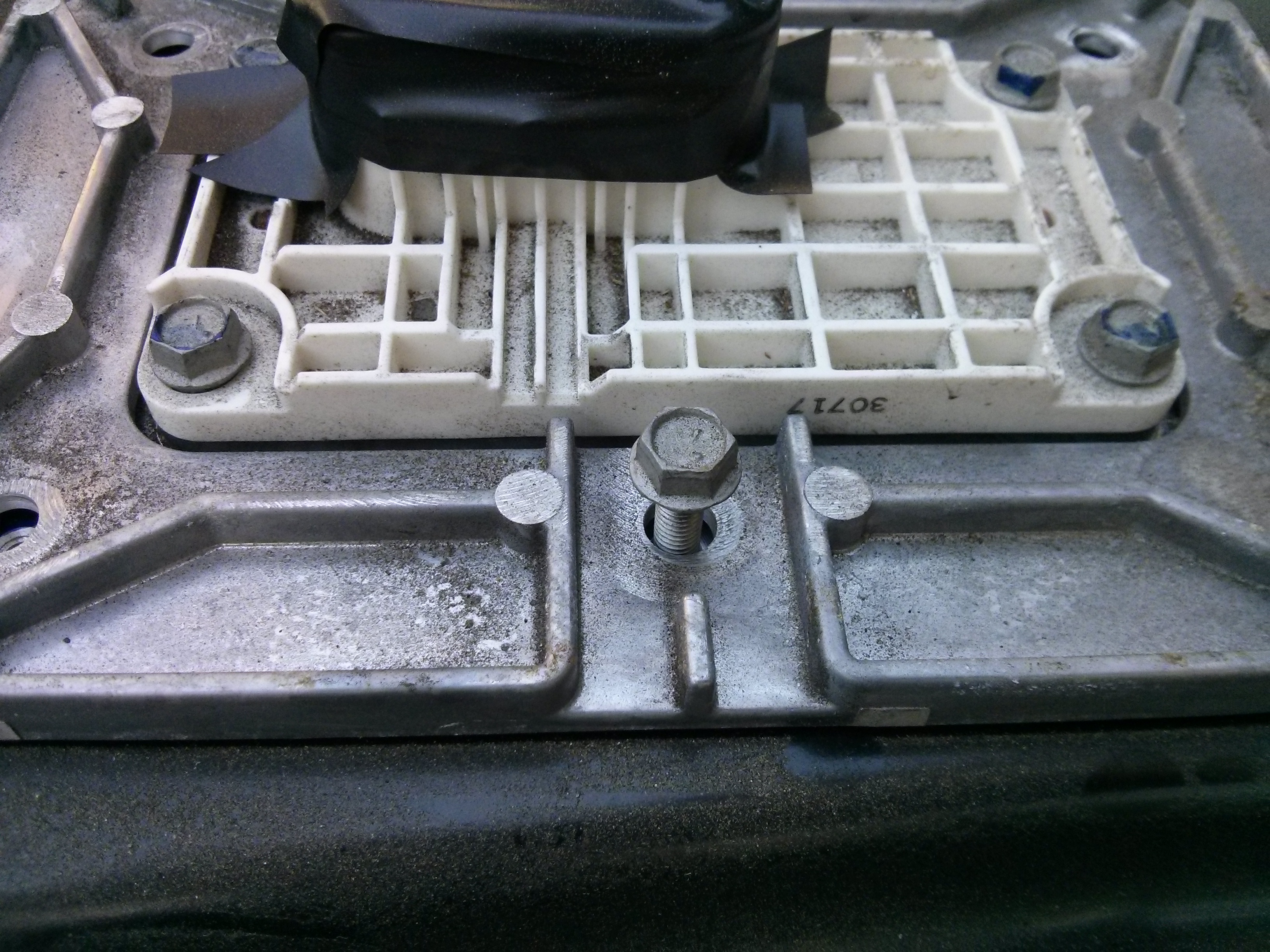
Sixth: You need to remove that large black steel bar. It is held on by two 16mm nuts (impact driver or hit a wrench with a hammer…) on the ends, and two 13mm nuts (need a deep socket, but a low torque normal ratchet is fine) in the middle. One of the middle nuts is close to a bus bar that goes through a current sensor on the way to the service disconnect, so use your HV insulated gloves on that one for sure. This bar goes over BMS wires and bus bars that connect the 2-high packs of 4 to the 4-high packs of 8 modules on the left and right sides.
Seventh: You can either disconnect the bottom plates from the battery shell, and lift the entire set of modules up, or you can disconnect the top plates from the bottom plates by removing the 10mm bolts on the top, and then manhandle the cells up and out of the battery. A hoist would make this procedure easier, but the busbars and plastic covers will flex a bit if you want to just lift stacks of modules out a little at a time. They are sitting on pegs, so you have to lift them up before you can drag them out. If you are manhandling the modules, you will probably want to wear your insulated gloves under regular leather gloves, as you will need to reach around the terminals/busbars at the top of the modules to lift them.
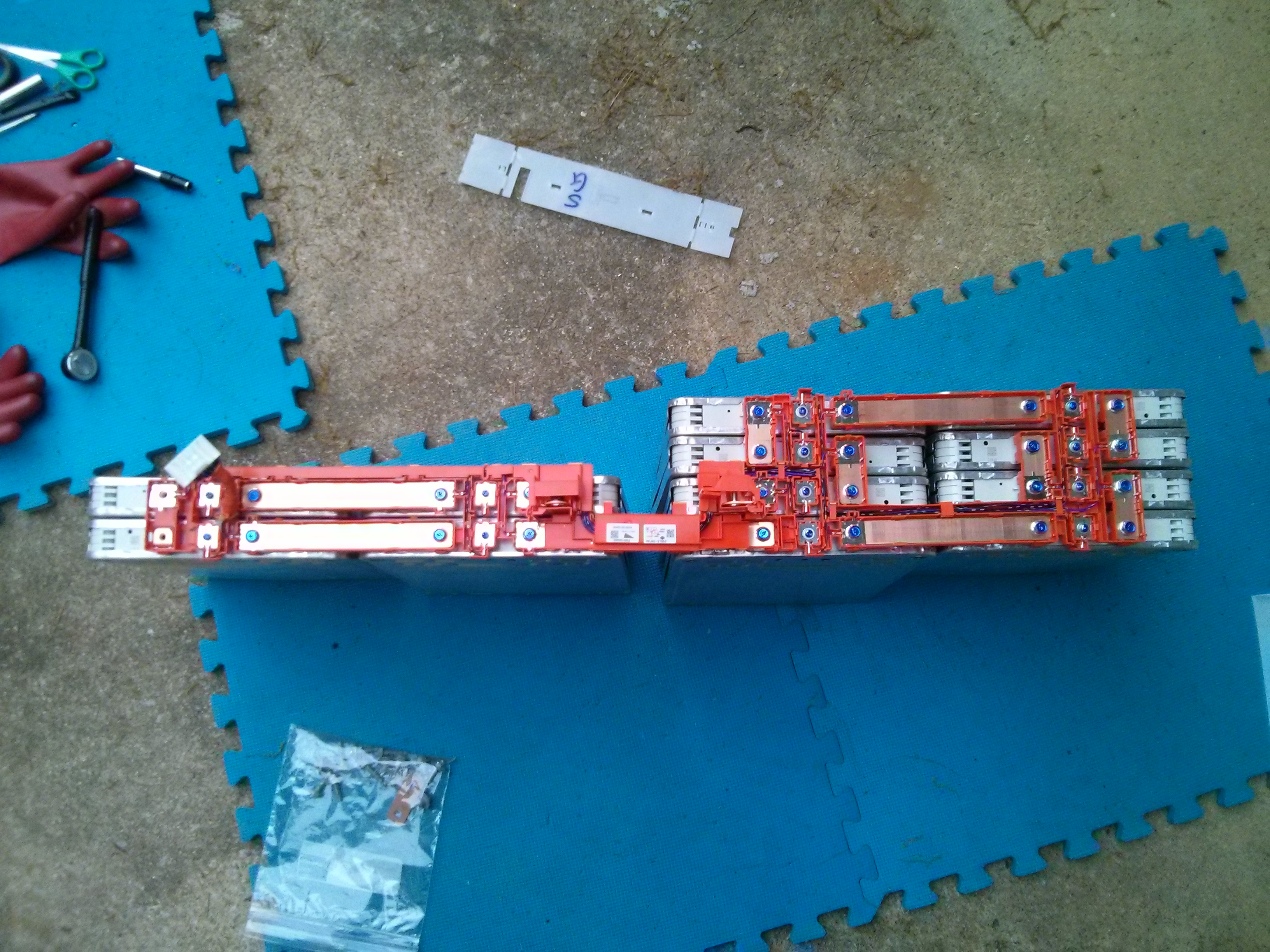
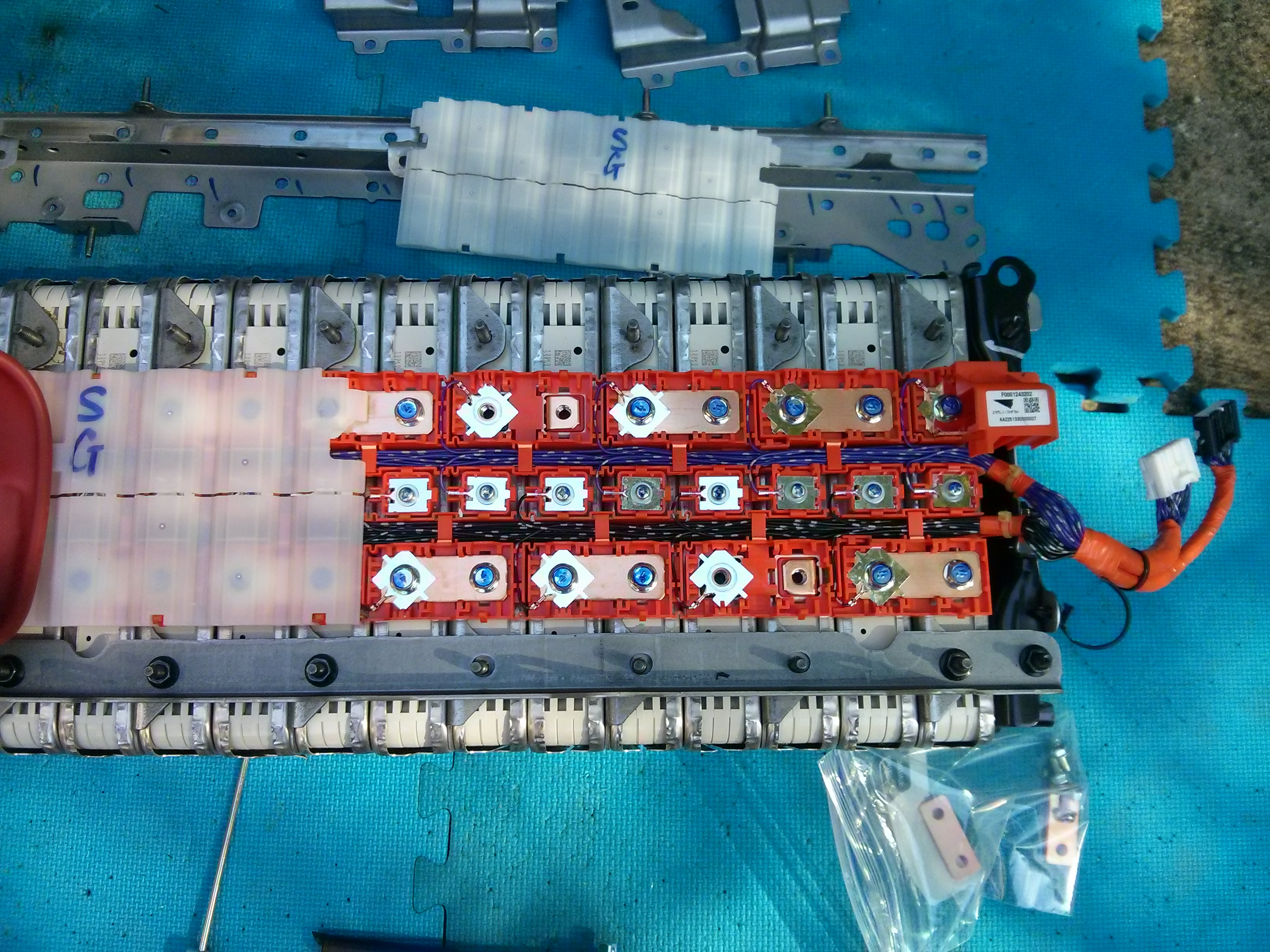
After you get them upright, it is easy to remove busbars to split the 12 modules up into smaller groups. However, after doing this for a while, I realized that it takes two bolts to remove a busbar, but it only takes one additional screw to release an entire module. Because the busbars are making serial connections between modules, removing a module is essentially the same as removing a busbar (in that the pack gets separated into smaller subpacks), and as an added benefit, you have a module removed, and the busbars are left in the nice orange plastic organizer. So I started just removing modules in such a way as to break the packs down into smaller and smaller parts. I put the bolts and screws back into the module terminals, and then taped over them with electrical tape.
Here is a picture of the serial busbar connections on one of the 12 module “side” set of cells (I have removed one short vertical busbar from the far left before the picture was taken).
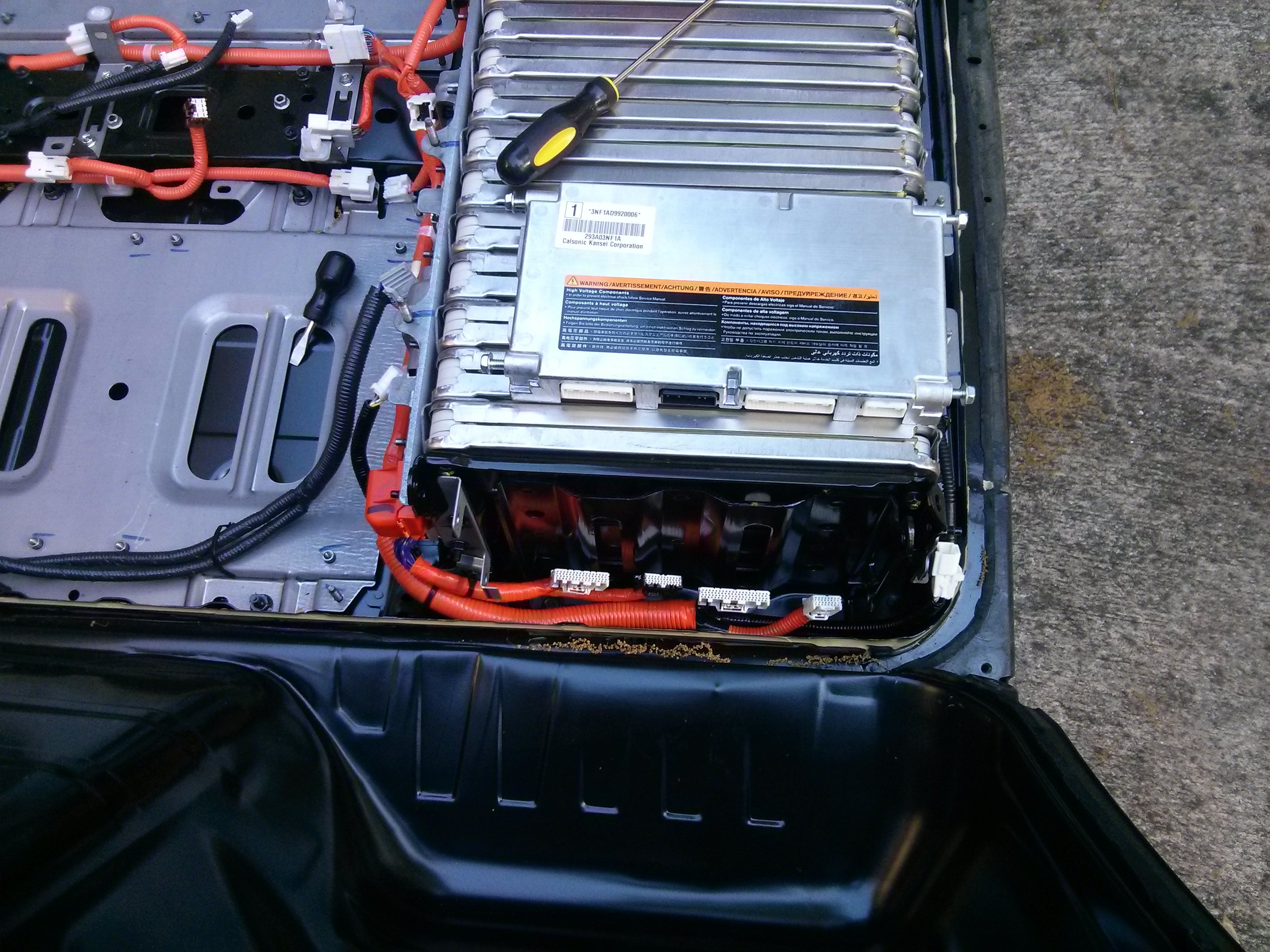
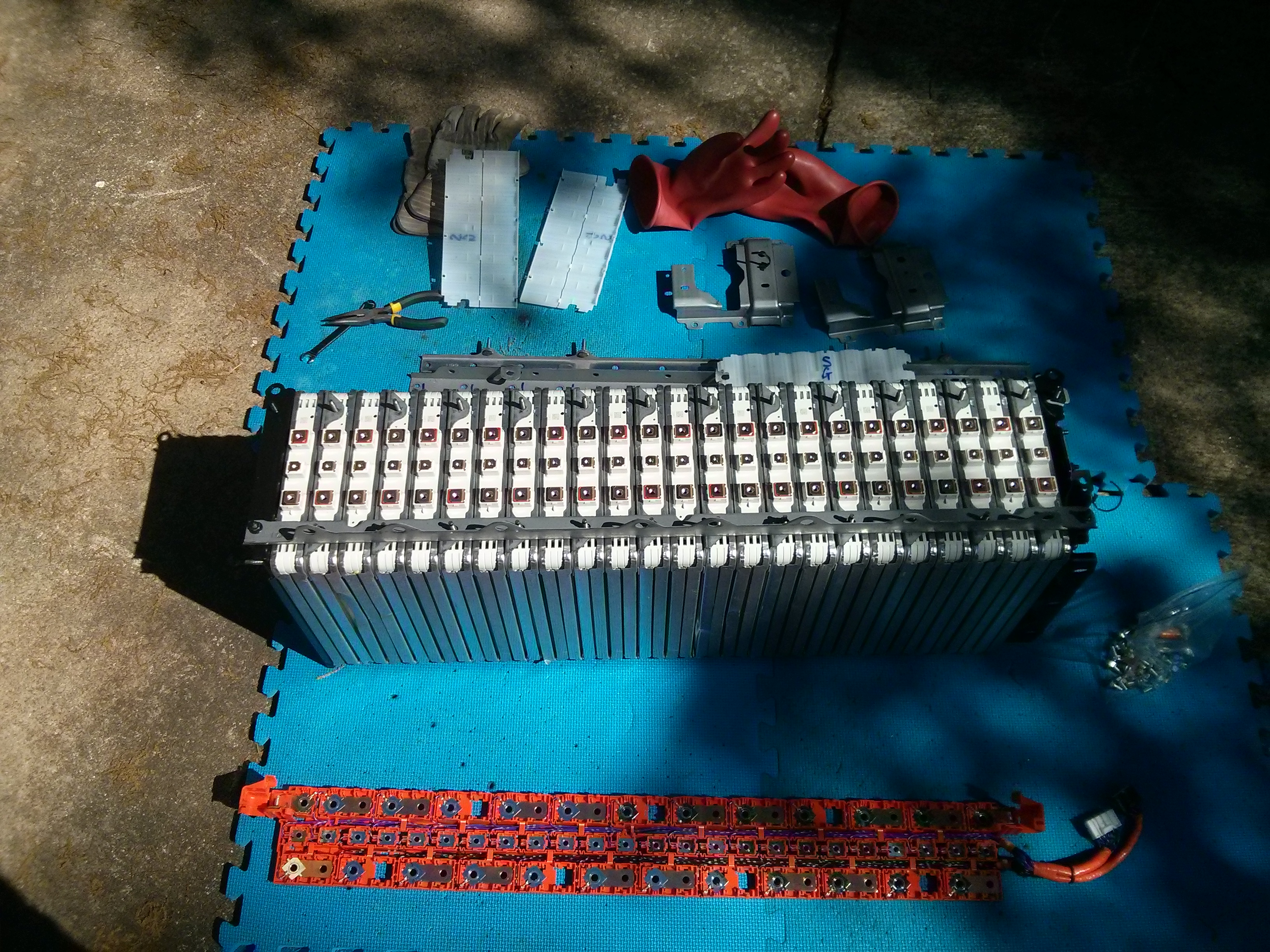
Eight: For removing the “back” pack of 24 modules, you need to unbolt it from the shell. It is held on with 3 13mm bolts on each side, plus eight 10mm bolts on the front and back (16 total). To get to the 3 bolts on the BMS side, you will probably want to remove the BMS unit, which is relatively easy. It has four plugs on the bottom and two on the side, and they all are easy to unplug. Just use one screwdriver to push the catch in, and another screwdriver to push the plug out. The wires have high voltage potential, but the plugs you remove are female, so they are relatively well protected.
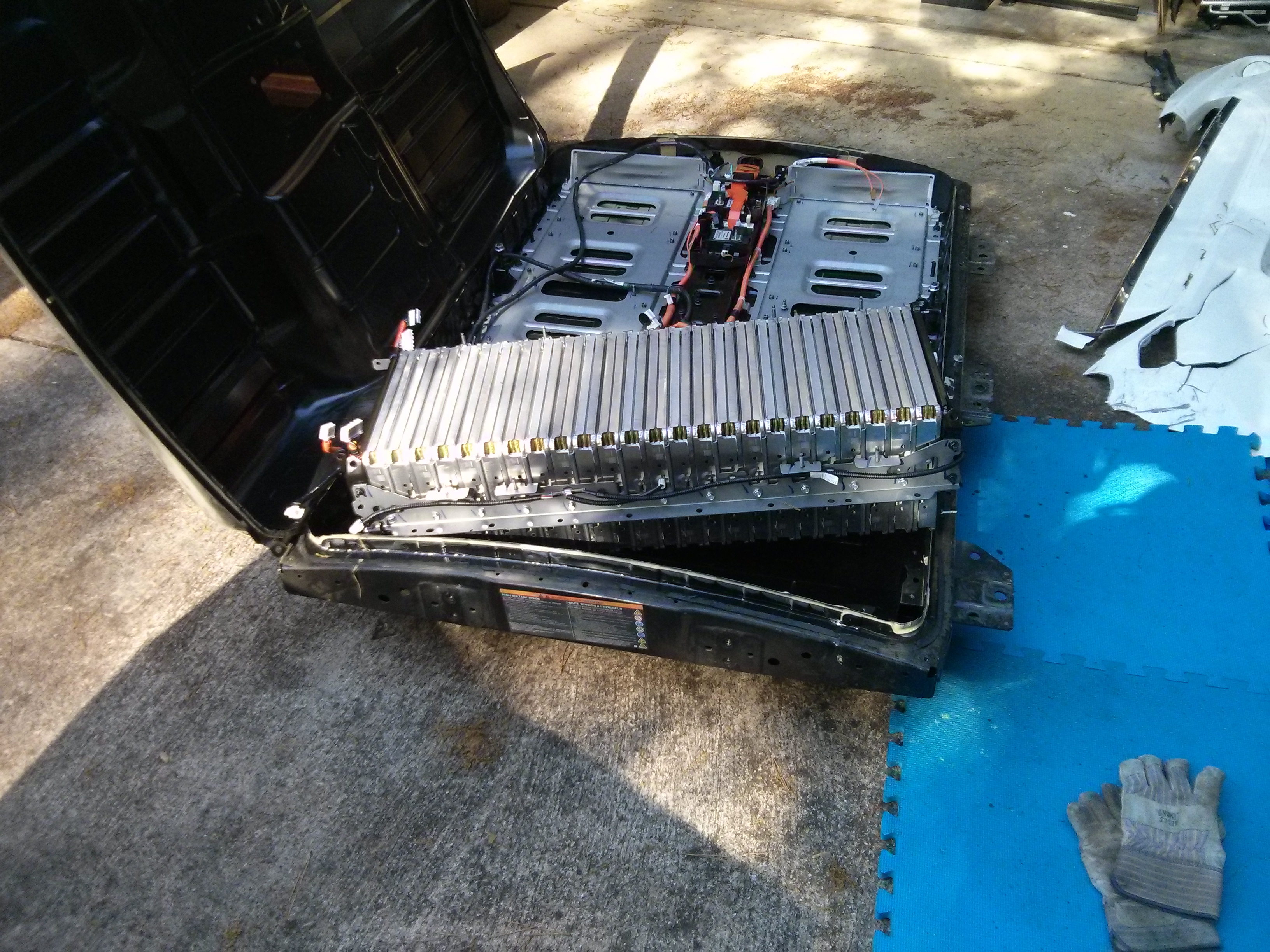
If you have a hoist, it is relatively easy to lift the entire 24 module half-pack out of the shell. If you don’t, it is possible for one person to lift a corner out, and walk the half-pack around a corner at a time to get it onto a mat.
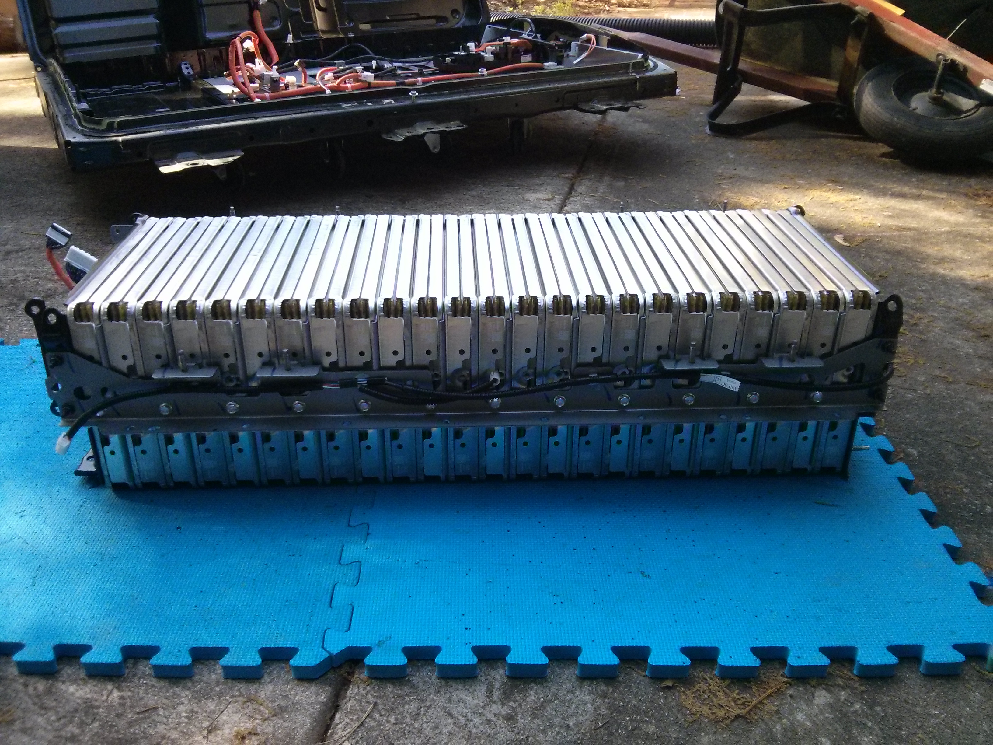
There is a bracket along the bottom that is bolted to the plates that are between every two modules. It will make it difficult to stand the pack of modules up to work on the busbars, so I took it off. It is held on with 12 10mm bolts and 4 10mm nuts (on the end).
Then, it’s just a matter of removing some plates from the top of the sub-pack. Two of them held on by 5 bolts each cover the bms wires and busbar guards, and must come off. One long one that goes across the top could potentially be worked around, but it has some protrusions that go over the busbars, and it is close to the plastic catches on the white plastic guards, so I also took it off.
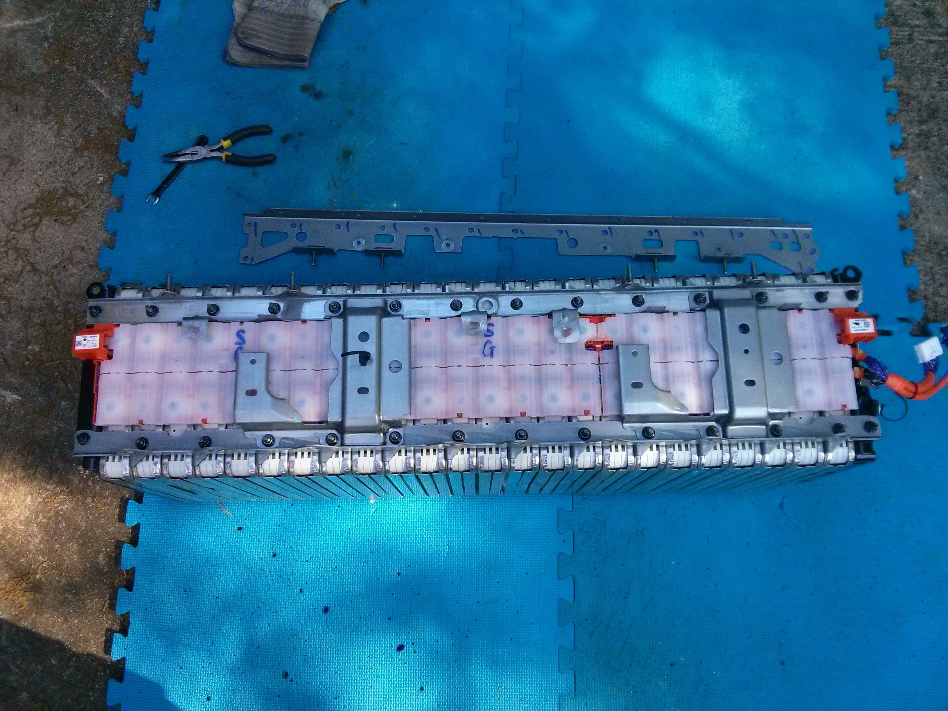
Ninth: Snap off the white plastic guards (one at a time) and start removing sense screws and bolts. I went ahead and removed every 3rd bussbar, separating the pack into 24 volt segments, and then snapped the busbars back into the plastic guard after I got it all the way off. After I freed up 8 of the modules, I slipped a piece of coroplast under the orange plastic guard, separating the busbars and sense tabs from the modules, and then moved on to the next 8 modules.
And at this point, it’s just a matter of moving the half-pack off to storage until you need the modules.
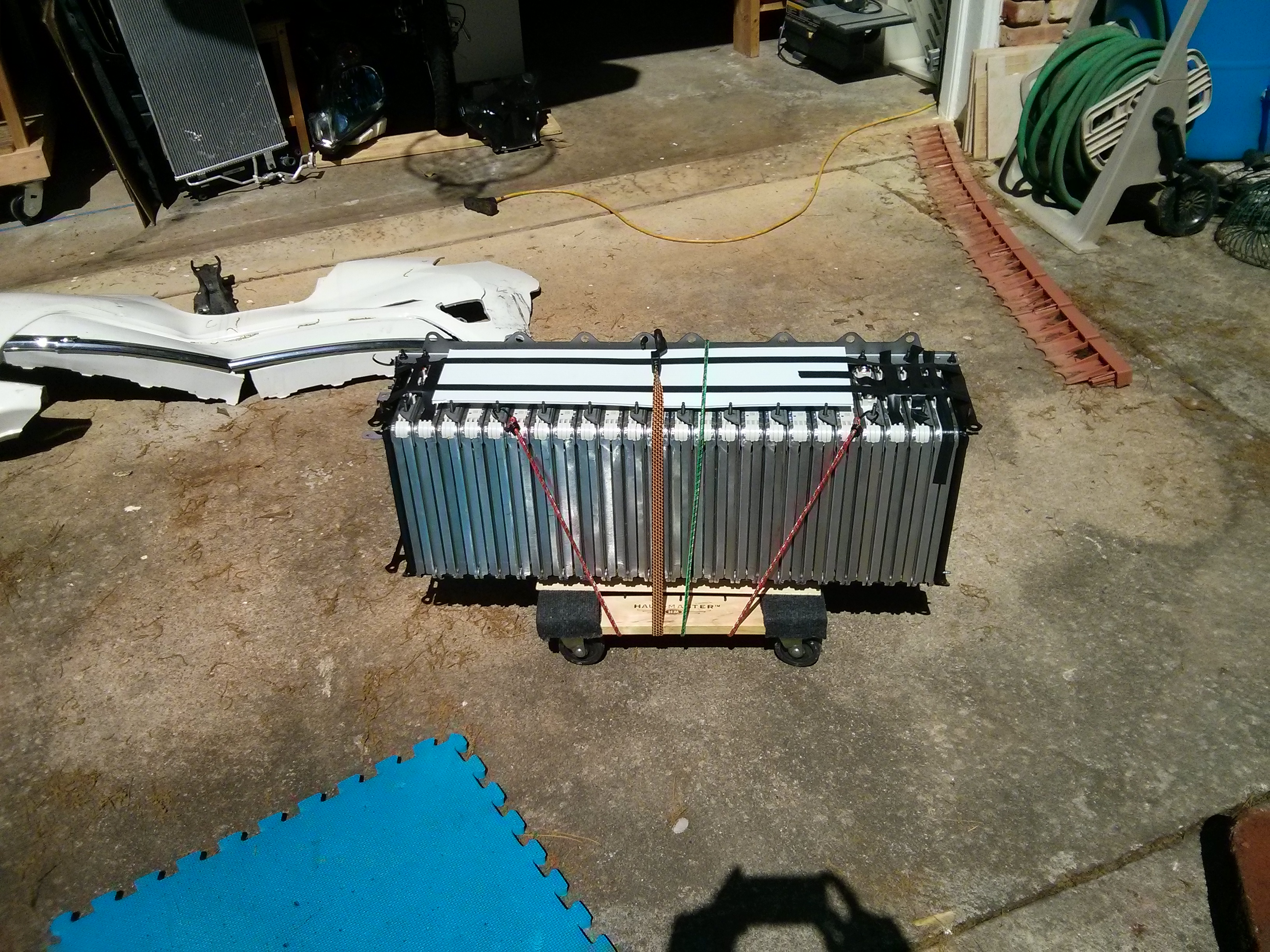
I measured just how “compressed” Nissan keeps the modules before I unbolted anything. The full set of 24 modules (with the separating metal plates between every two cells) was 32 inches when measuring at the corner. Six modules was eight inches, and 12 modules was 16 inches, so I think it’s safe to say that 1.33333 inches per module is a good compression to aim for.
The busbars are 1.61mm thick, and 20mm wide, and appear to be made of solid copper. So apparently that is the size you need for 250 amps at 400 volts. The smaller busbars are 54mm in length, have 7.8mm hole diameters, and I believe the holes are on 34mm centers, which is 1.33858 inches, or perhaps just 1.33333inch centers. There is a bit of slop in the holes around the bolts anyways.
Other than the modules themselves, there are some other interesting things inside the battery.
If you unbolt the service disconnect and turn it over, it has a 500 volt DC fuse rated at 225 amps (I don’t know if that is a slow or fast blowing fuse…)
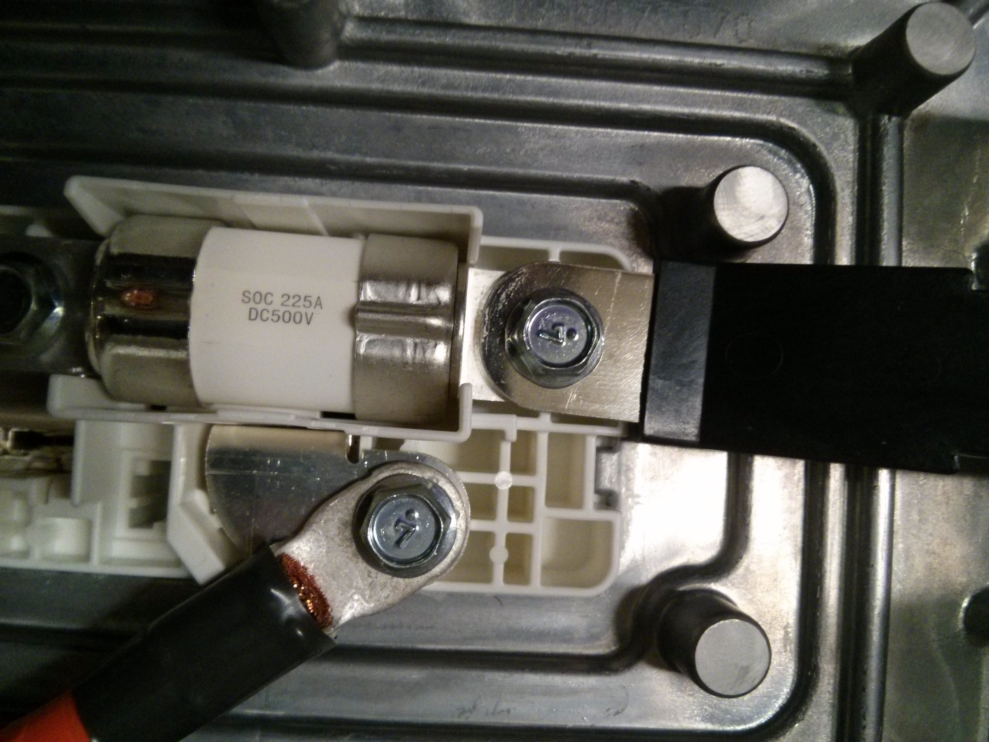
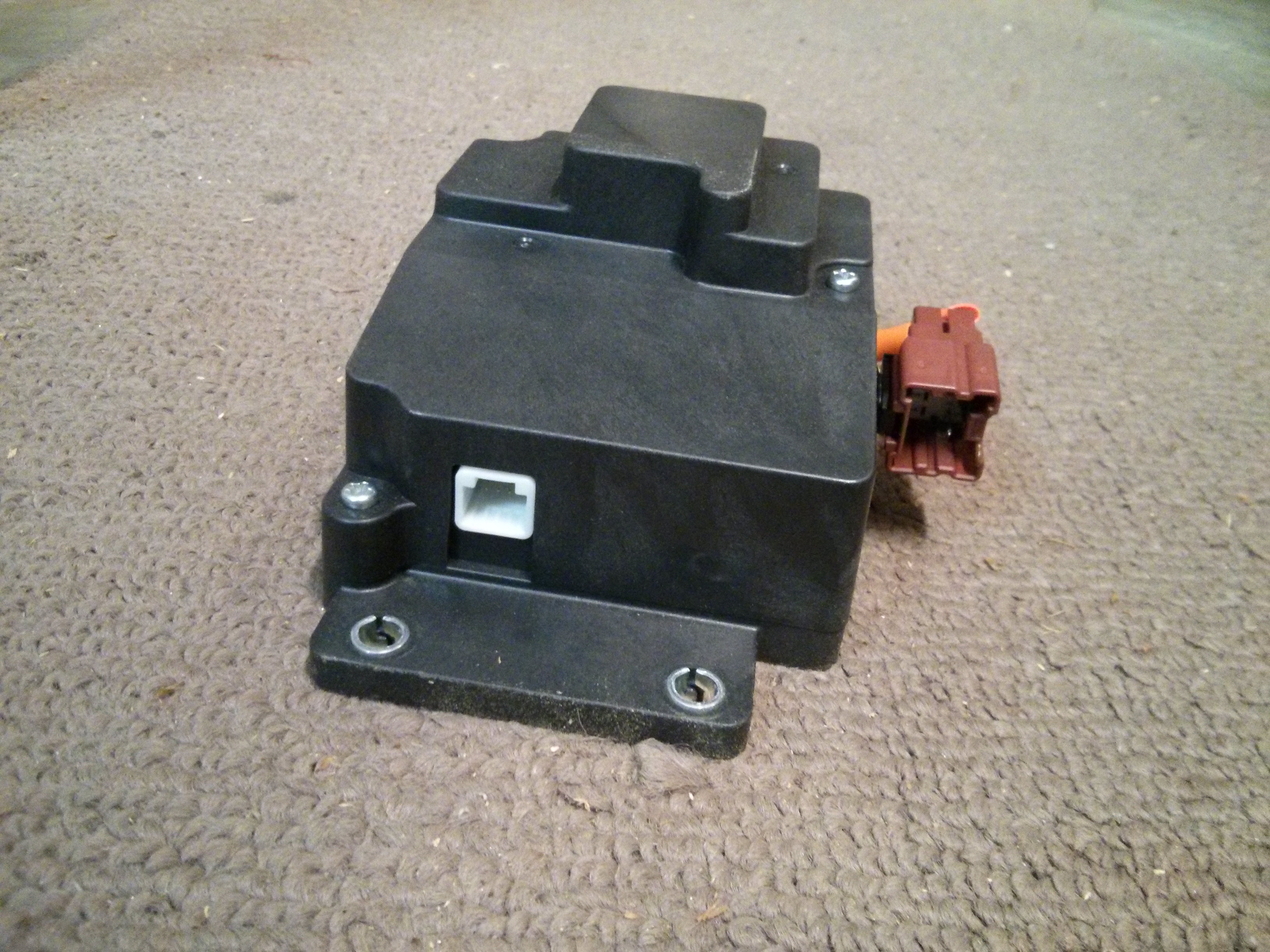
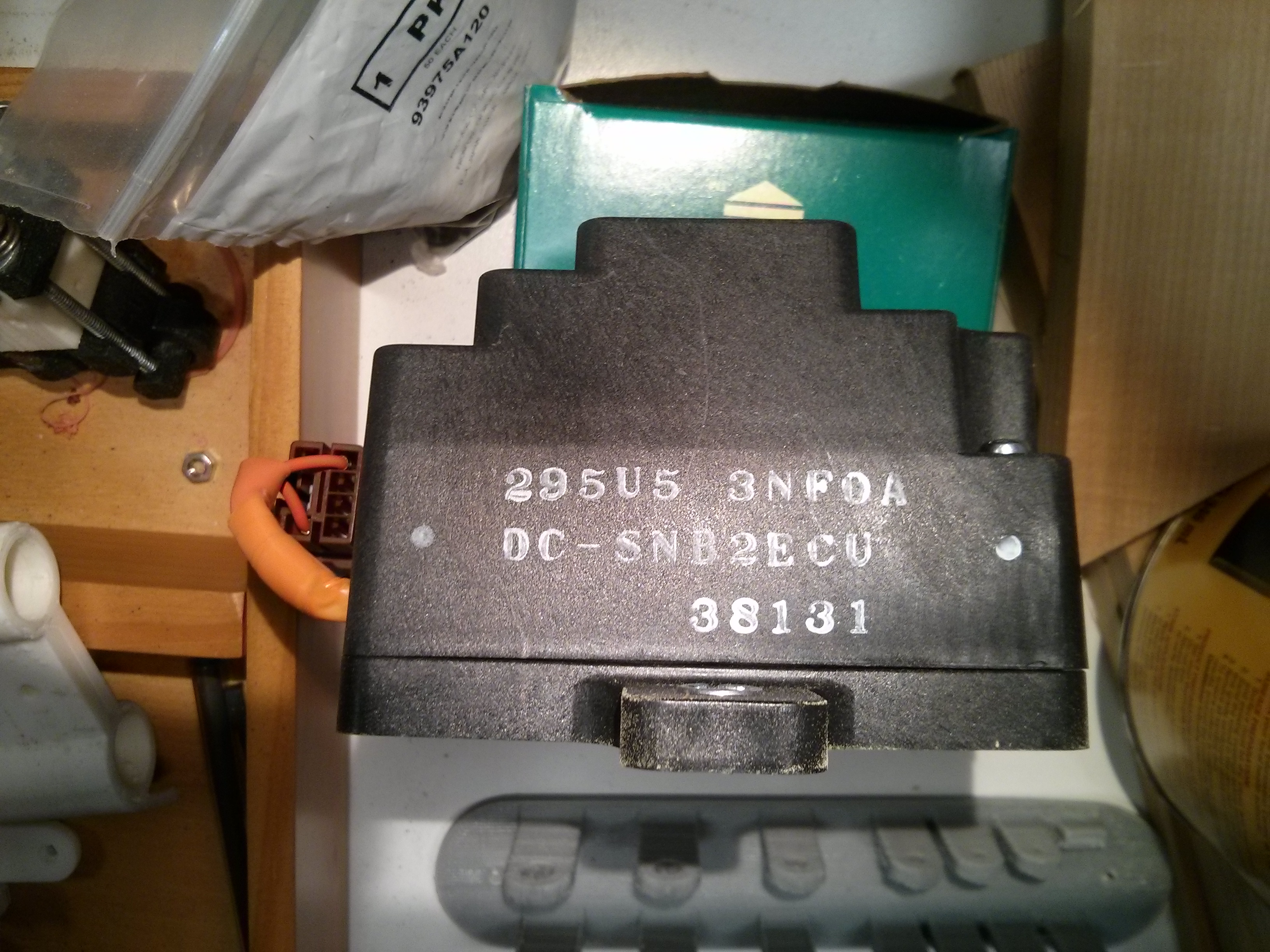
Also under the service disconnect is a box which switches the 400+ volt power on/off to either the resistive heater elements or the cabin heater (sorry, I didn’t trace the wires coming out of it…). Inside it has a 500 VDC 5A fuse and a large relay controlled by a circuit board. (Markings on the outside are: 295US 3NF0A / 3NFOA DC-SNB2ECU 38131 )
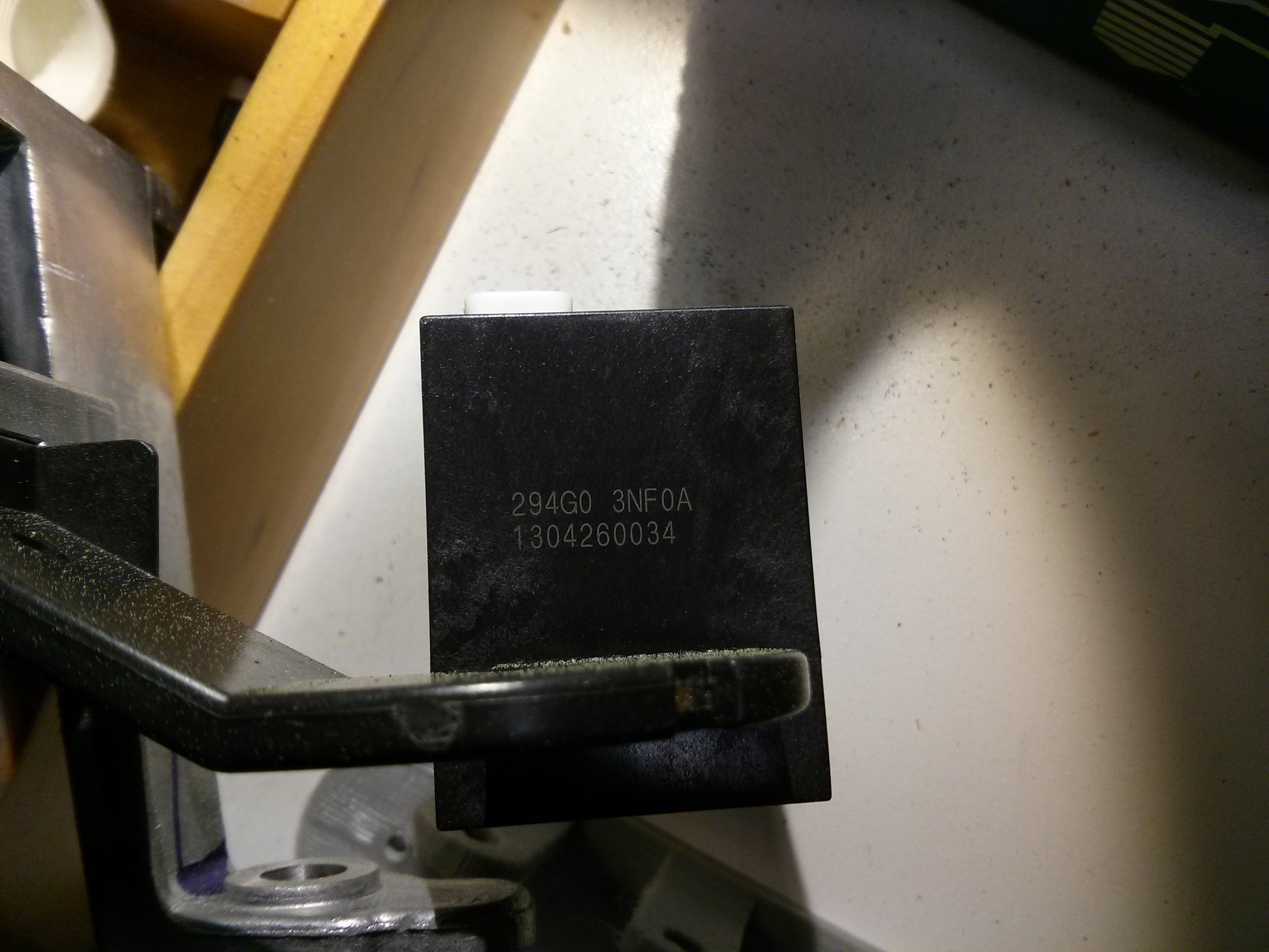
Also, mounted on the busbar going to the service disconnect is what looks to be a current sensor. Funny enough, the numbers on the side of it match up to a current sensor that one online website says is connected to the 12 volt accessory battery, so perhaps the same sensor is used in two different places…or perhaps they got their numbers mixed up…( 294G0 3NF0A 1304260034 )

Near the front of the battery is the main contactors on both the positive and negative side (Panasonic AEV6505A) which I assume are rated for at least 250 amps at 400-500 volts, although I haven’t been able to find a specification sheet for them online.
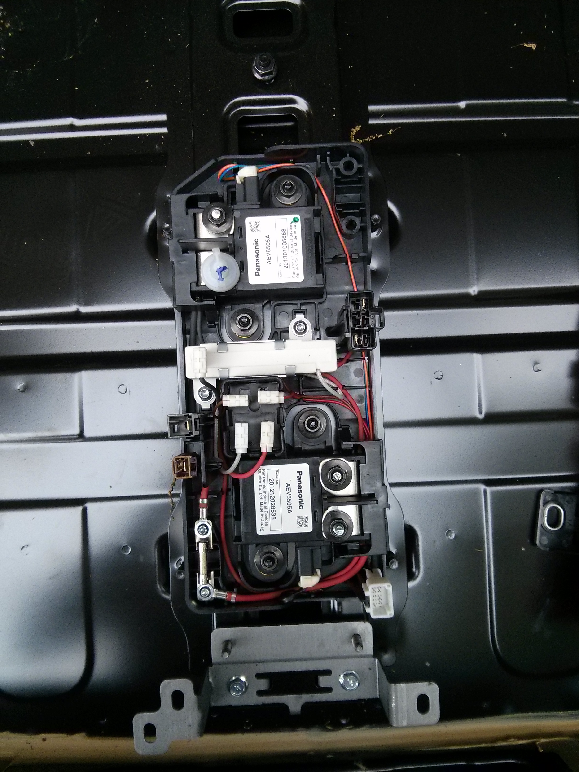
There is also a smaller relay/contactor for the pre-charge circuit. (AEV6501C)
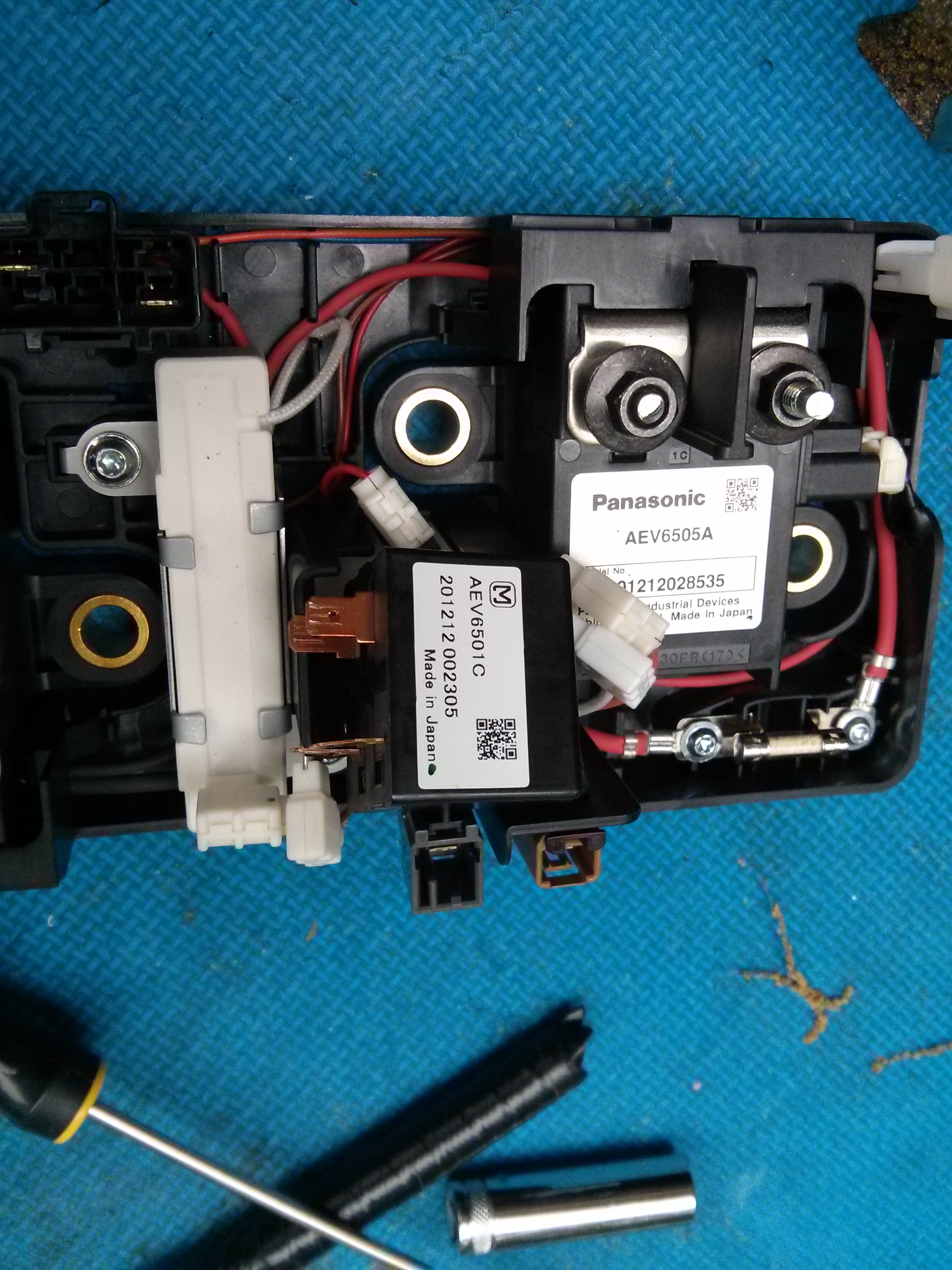
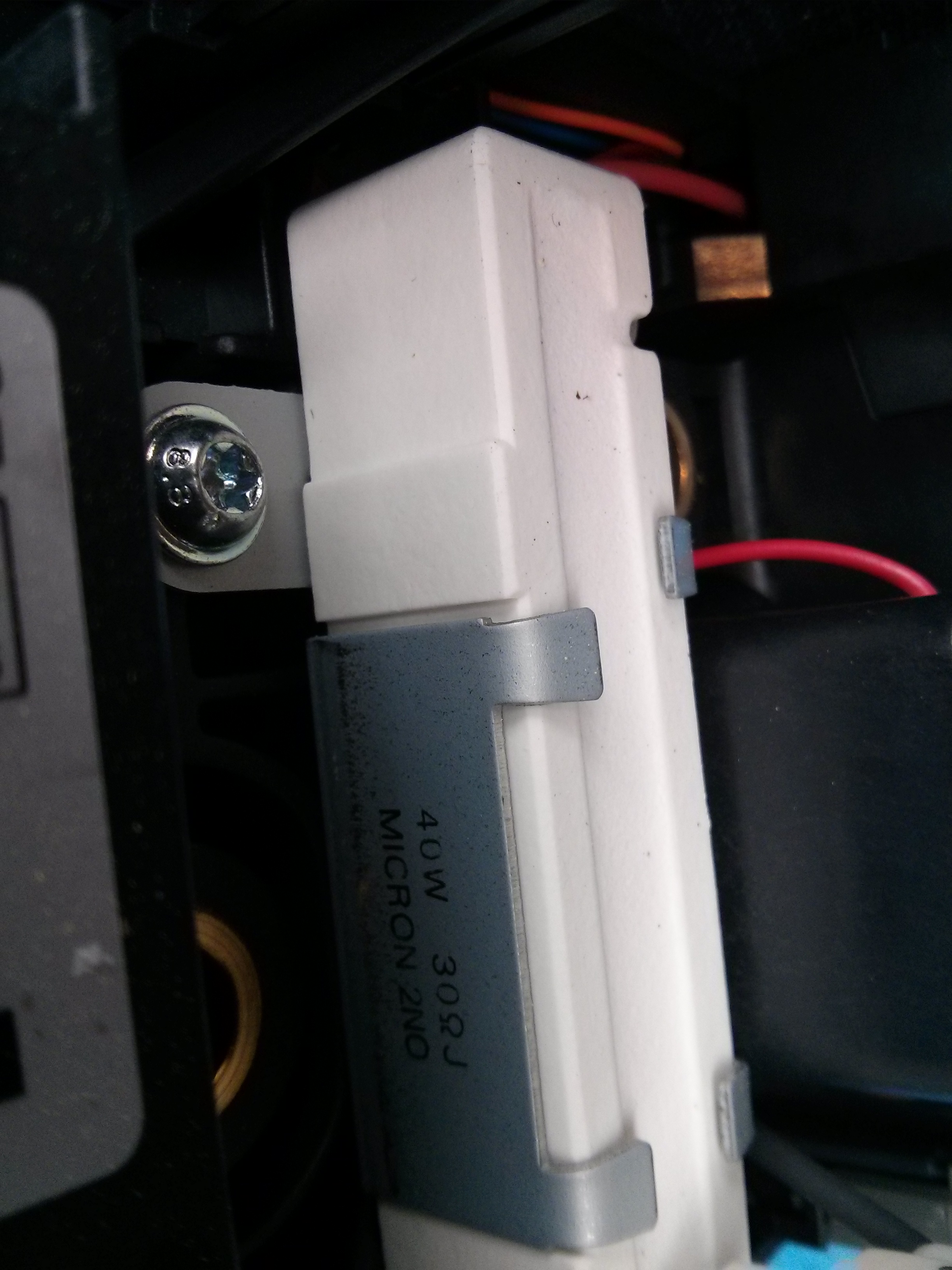
Which is connected via a 40 watt 30 ohm power resistor. (400 volts at 30ohms is 13 amps?) I believe the “J” after the 30 ohm is a +/- 5% on the ohm rating.
And of course, the 96 cell Nissan specific BMS unit and associated wiring, which I’m sure costs a good amount to manufacture, but is basically useless to a hobbyist until somebody reverse engineers the CAN bus signals.
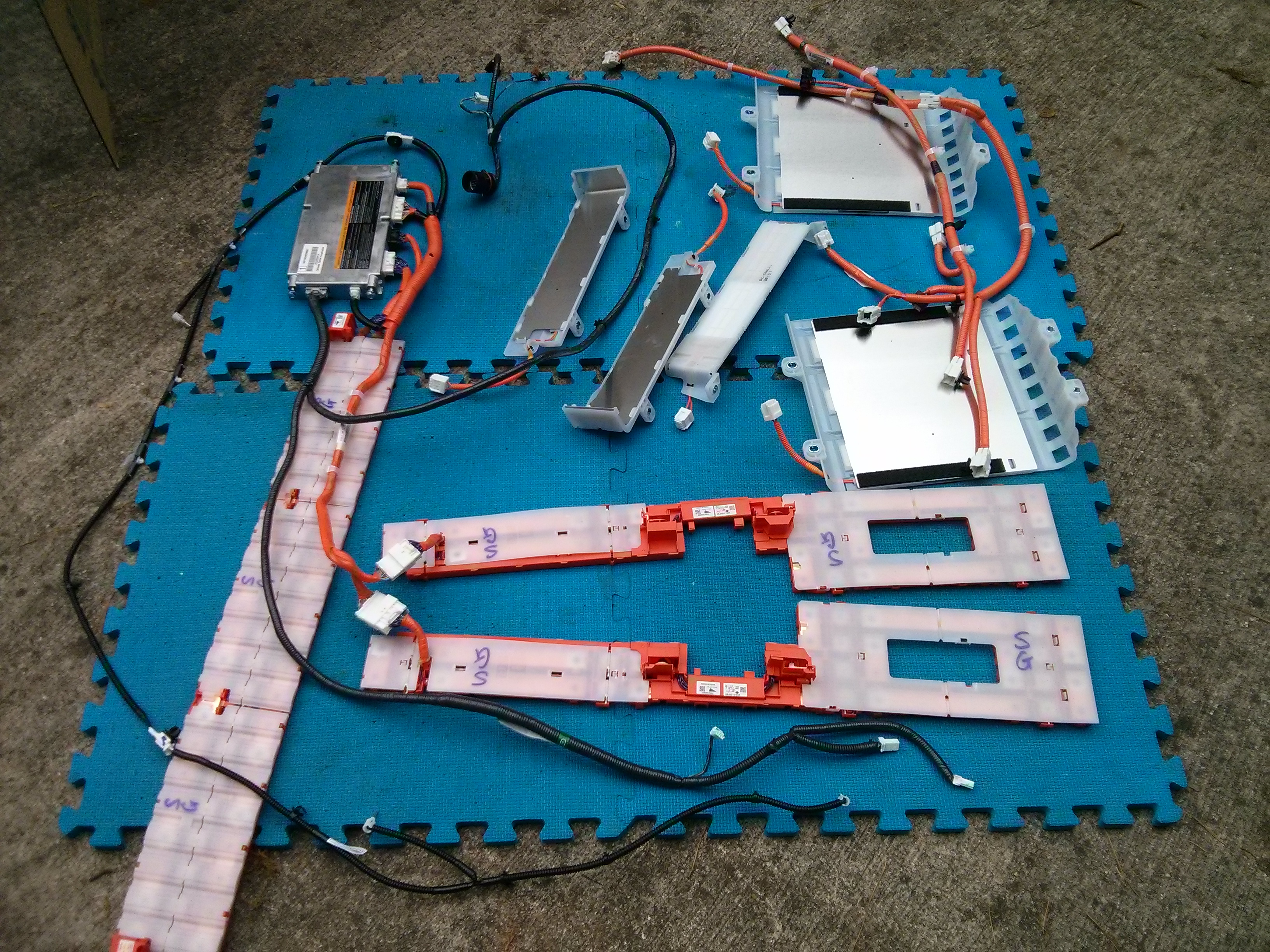
They do have a lot of copper busbars, but they are only useful if you are using the packs in series of 60 Ah modules just like Nissan. I plan on using 3 parallel modules to make 180 Ah “batteries”, so my busbars will need to be able to handle 2-3 times the current that the stock ones do. (Although I’m sure they over engineer things, I have a 120 volt high amperage system on my S10 pickup, while they have a 400 volt not as high amperage system.)
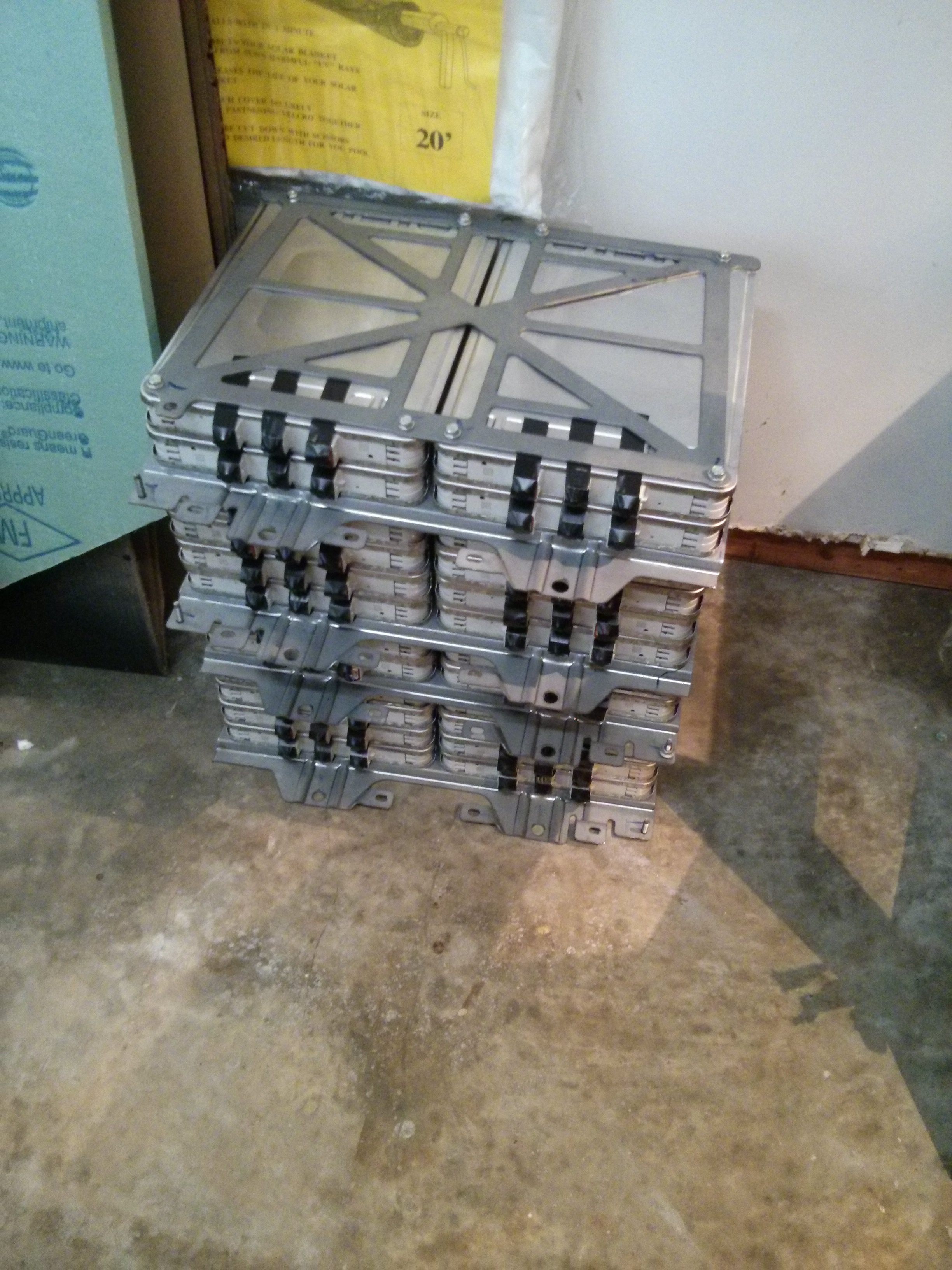
Until then, I am using the metal plates that came out of the batteries to store the modules.

")


Continuing to follow your progress with great interest. The photo essay you are building is invaluable!
One question: Does there appear to be any anti-oxidation/conduction grease or other compound on the busbar terminals, or are they bare copper-to-copper?
Am starting to research the purchase of a wrecked Leaf for the same purposes.
I saw absolutely no evidence of any type of coating or grease on the terminals, it looks to be (very shiny) bare copper to copper. (I wouldn’t be surprised if the buff the copper right before assembly.)
Interesting…
Secondary question:
Were you able to measure the amount of torque necessary to remove the screws securing the busbars to the module terminals? I suppose that somewhere, someone has the torque spec for reinstalling the (new) busbars, and tightening the fasteners?
No, I didn’t measure that. They were relatively easy to remove with just a hand ratchet. A single sharp turn at the beginning and they were free.
What do you plan to do with these cells?
I will eventually be replacing the lead acid golf cart batteries in my electric S-10 pickup with them. I currently have 20 six volt golf cart batteries in the truck, and I will be replacing them with 16 packs of 3 modules in parallel to get a similar voltage/amperage to my current setup.
Hey Jay. I enjoy your project. I would like to build a solar battery like this for my home.
Is it possible for you to post or send me some pictures of the actual battery BMS connections or (drawing), I thought it would be one bms per battery but looking at your pix it doesn’t seem so.
Thanks for posting your project.
I just added a post about the BMS system.
https://www.summet.com/blog/2015/12/03/16-volt-nissan-leaf-battery-management-system-bms-information/
You may also find the “building the battery” post useful:
https://www.summet.com/blog/2015/10/31/how-to-build-a-16-volt-battery-module-from-six-nissan-leaf-cells/
I have a question that I can’t seem to find the answer for anywhere. On the picture underneath the seventh step, there are three connectors. It is my understanding that from right to left is the low voltage connector, high voltage connector and ‘connector for extended high voltage (CEHV)’. The latter connector, CEHV, is not present on the first generation Leaf battery so I wondering if you can provide a little more insight into what it’s purpose in the battery is.
Thanks,
Jack
The far right connector is CAN bus and 12 volt pins for various contactors, etc. The large center connector is the motor High Voltage connector. The for left connector is also a high voltage connector with it’s own (smaller) contractor, (I believe this is what you are calling the CEHV) and it supplies power to the resistive cabin heater element.
I am looking for the 96 cell bus bar battery cables connector for the Nissan leaf. Let know how I can get them from you.
Thank you.
Sorry, I’ve already sold those (and most other) parts from the battery.
Jay did you think about and intimately decide against fusing the individual modules? I am building a system for home power (Powerwall-ish) and I have been back and forth. I thought about fusing the modules or module groups. I will be running a BMS with the ability to remotely disconnect the battery. Thoughts?
I have two fuses in my truck. One up front near the motor controller, and a second fuse in the back at the midpoint of the battery pack between two modules. Each fuse you install adds a small resistance power loss to your system, so it is always a trade-off between safety and cost/performance.
There is a (small) danger in putting the modules in parallel without a fuse. (If one of my 3 modules were to short closed, the other two would dump their current into it). However, I’m counting on the inherent safety of the Leaf chemistry, as well as the observation that internally each module Nissan made has 2 pouch cells in parallel in the same way.
On the other hand, my truck is NOT located inside my house (I park it outside, as I need all the the garage space for more important things ;>), and if I were to build a powerwall type setup that was designed to be inside my house I might use a carefully calculated (smaller) gauge wire such that the wire itself would work as a fuse. In a powerwall situation you have the advantage that the difference between the average and maximum current draw is a much smaller range than in a motive (EV) situation, where my average draw is 50-80 amps, but my maximum draw can be higher than 400, which makes fuse selection more difficult.
You mentioned about separating metal plates between every two cells. what does that exactly mean. I want to know if all the modules which are stacked have any foam or plate in between them or is it just module to module packing.
Also, by any chance, were you able to determine the thickness of the metal used in the enclosure of the battery pack or the module? Would be great if you can help me out, thanks.
The 24 modules in the back of the battery (the largest collection of modules) have flat metal plates between every two cells for the purpose of physically mounting that set of 24 modules to the case. The shorter “horizontal” battery stacks in the rest of the battery do not have them. These metal plates do not increase the thickness of the stack of modules as there are 12 “special” modules which are designed to accommodate them.
You will want to read this post which gives photos and examples:
https://www.summet.com/blog/2015/09/27/leaf-battery-module-differences-36-normal-and-12-special/
I did not measure the metal used for the exterior of the battery pack. It was relatively thick sheet metal, possibly as thick as 1/8″.
Pingback: Salvage 2013 Nissan Leaf Modules – 8 year age capacity test: 75-80% | Jay's Technical Talk
Hi! dont you know about thespec sheet of “Panasonic AEV6501C” and “Panasonic AEV6505A”?
I haven’t looked at those, no.
hellow have you from 2014 up manufacture BMS ?
Sorry, the BMS from the 2013 Leaf Pack has already been sold.