I am in the process of replacing the twenty (20) six volt lead acid golf cart batteries that power my electric pickup truck with 48 Nissan Leaf battery modules. Because the battery bays in the truck are specificity designed to hold 20 golf cart batteries (and the Leaf modules have a different form factor), it’s not a straight-forward drop in replacement.
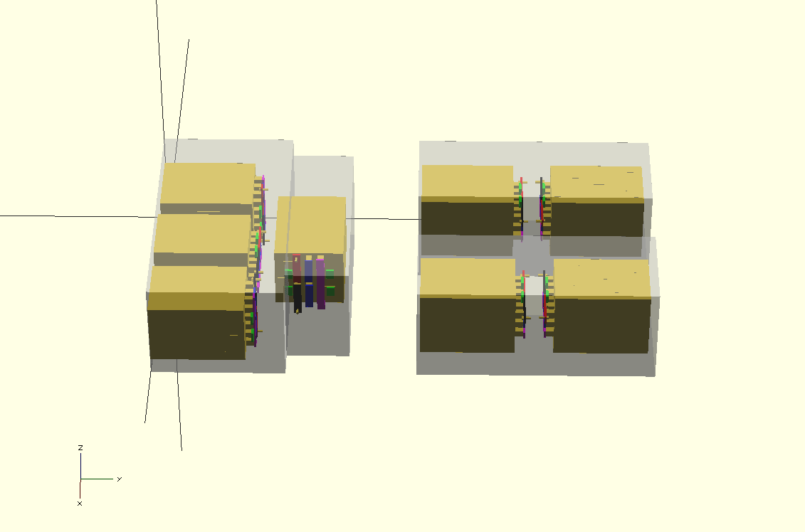
My initial design (not showing the compression plates that hold the six modules together in compression):

In the image above, the black bar is negative, the red bar is positive, the purple bar is connecting the two sets of 3 in series (positive to negative), and the blue bars are joining together the sense connectors on the 3 parallel modules. Just to confuse things more, the modules are actually made up of internal cells in a 2P2S configuration…so we care about the “middle” voltage of the series.) The green boards show one possible position for the miniBMS boards.
Other complicating issues involve the need to hold the leaf modules in compression, and the requirement of installing a battery management system (BMS) that connects to each module. Also, the leaf modules are only 60 AH, and I have decided to provision 180AH of capacity for my pack (due to the overall system voltage being limited to under 145 volts by the current motor controller and DC-DC converter) so I am having to put sets of three modules in parallel.
3 modules in parallel gives me 60Ah * 3 or 180 Ah. Since I have 48 modules (a complete 2013 Nissan Leaf battery pack) I can make 16 sets of 3. I’m grouping two sets of three into an 6 module “battery” so that they are reasonably sized and I have fewer “things” to build, move around, and connect with heavy 00 welding cable.
Due to the 8 lb weight of each module, I decided to build a “battery” using six modules (two sets of 3 parallel modules, wired in series). This will give each battery a nominal 16 volts and 180 Ah capacity, while keeping each individual battery to a manageable 50 lbs.
The only problem with this plan is that I’m 95% certain that I won’t be able to mount the batteries vertically. The Leaf modules (at 13″) are taller than a regular Golf Cart battery (10-11″), and my battery boxes don’t have much extra vertical room. I *may* be able to put them in vertically if I can keep the buss-bars and associated connections very short, and have absolutely no insulation or air circulation space on the bottom of the battery box. But I’m almost certain that I’m going to have to lay the battery units sideways to make them fit. This adds extra complexity in wiring.
Here is a CAD model of my existing battery boxes with 8 batteries (8 x 6 modules per battery = 48 modules) on their sides. Luckily for me, the Lithium Ion modules take up less volume (and weight) than the lead acid golf cart batteries they are replacing.
This will fit the 8 batteries I need into three of the four existing battery bays. I’m planning on placing my updated charger in the current front battery bay (not shown in the diagram) under the hood.
I would much prefer placing 3 battery units (18 modules) in each of my side battery bays (leaving only 2 in the rear bay) as this would move more of the battery weight forward of the rear axle. My S-10 pickup will never handle like a sports car…but with the Lithium-Ion upgrade I’m dropping a lot of battery weight so I expect the truck to get a bit more sprightly and would like to improve the handling if possible. As I’m removing 4 lead acid golf cart batteries from under the hood, I’d like to move the CG of the remaining batteries forward.
That’s the plan so far, which I’m sure will get modified as I actually start building a test battery. See my next post for the actual physical mockup battery I’m building.


Why do you need to hold the batteries “in compression” – is that for mechanically holding them together? Anyways – I like what you’re doing – email me, and I’d love to post this on hackaday when you have some solid progress and are near the end goal. Cheers. georgegraves@hackaday.com
I am using it as the mechanical mounting system, but you must hold LiIon cells in compression for proper operation so that they don’t “bulge”. So I was careful to measure that 6 modules in the Leaf battery pack were exactly 8 inches (1.333 each) when compressed. They are slightly thicker just sitting around.
I don’t know for sure if they need to be held in compression in storage (I don’t think so, but I’m doing it anyways just in case) but I have heard a lot of people say they need to be compressed in usage (charge/discharge). I plan on having a few more process posts (building one using the final system, creating 2/0 cabling to connect them, final CAD design for the layout) and then a final post that will show the actual installation in the truck.
As I’m working full time, and the current Lead Acid battery pack is still working (for now) I’m not in a terrible hurry to get it done. So I’m taking my time and trying to plan everything out so that I can make the switch in a single weekend without having to go buy extra parts, etc… (Also, in Atlanta, working outside in October is a lot nicer than in August ;>)
I am planning on replacing my 8 Trojan L16 battery bank with 20 of the leaf modules. The modules will be wired in pairs so I will have 10 12 volt batteries (15.2volts actually) Do you have a recommendation on a mini BMS that I should use on this reconfigured bank of modules. I figure I will need 10 of the BMS for the complete bank. I have been looking around the internet at various BMS and find I am getting confused. I am using 2012 Leaf modules, 7.6 volts 50 AH
I believe that the L16 are 6 volt batteries, so 8 of them (I presume in series?) would be 48 volts nominal, around 300-400 amp hours. This sounds like a golf cart sized application.
Note that the leaf modules are NOT 12 volts, but instead are 7.6-8.4 volts each, (60 AH). So if you put 10 buddy pairs of them in series you would get 76-84 volts.
Note that the leaf modules actually have TWO cells inside them, so you would need two BMS modules for each leaf module. If you put 10 leaf modules in series, you would need 20 BMS modules.
If you are trying to replicate a 48 volt system with close to 20 leaf modules, I would suggest using six series sets of (3 modules in parallel) (18 total modules) or six series sets of (4 modules in parallel) (24 modules). Each leaf module is around 0.5 kwh of capacity, so you would want at least 3-4 of them to replace the capacity of each of your L16’s.
To answer your BMS question, the miniBMS that I used is no longer in production, and I don’t have a good suggestion for a replacement, although I have heard good things about the Orion line.
I recently purchased 56 of the leaf modules and will be using them in 8P14S (7 stacks of 8 modules in parallel). I am using them in a 48volt solar battery bank application. Since I am in the configuration stage and did not receive any of the spacers I had a friend cut me 126 spacers out of .25″ aluminum. The .25″ aluminum is twice as thick as the spacers that are used in the original Nissan battery packs. My thinking was that I could avoid the inherent overheating problem that these modules had in the original car battery configuration by adding a bit of an air gap between the modules in the stacks. I originally came to this thread to verify that compression is not needed. I have no previous experience using Lithium batteries. So when you say they require compression are you saying this from your experience or is it some design requirement that the manufacturer said is required for these modules. I also purchased a Batrium BMS for my system these folks offer a couple options for the leaf batteries depending on your configuration.
Compression is REQUIRED (by the manufacturer and my experience) whenever you are charging or discharging the modules so that the pouch cells inside do not expand/burst. [I’m not sure if they are needed for storage, but I’ve always stored them compressed as well….]
I only needed the spacers near the top of the modules for those from the rear of the battery pack. Most of the modules fit “module2module” without spacers between them. [BUT, compression END PLATES are necessary.]
In an off-grid / grid tie solar battery bank application I doubt you will need any extra cooling. The cells can be fully drained in ~ 1 hour time when driving in a Nissan Leaf, if you are charging them up or discharging them in a 5-10 hour time they won’t warm up enough to be an issue. 8 modules in parallel is 60ah *8 = ~480aH and you have ~28 kWh of storage capacity. So unless you plan on repeatedly charging and draining the full 28 kWh in an hour, I doubt very much that you will need extra cooling. [If you do, just extend the aluminum spacers past the end of the modules and cool the spacers with a liquid loop.]