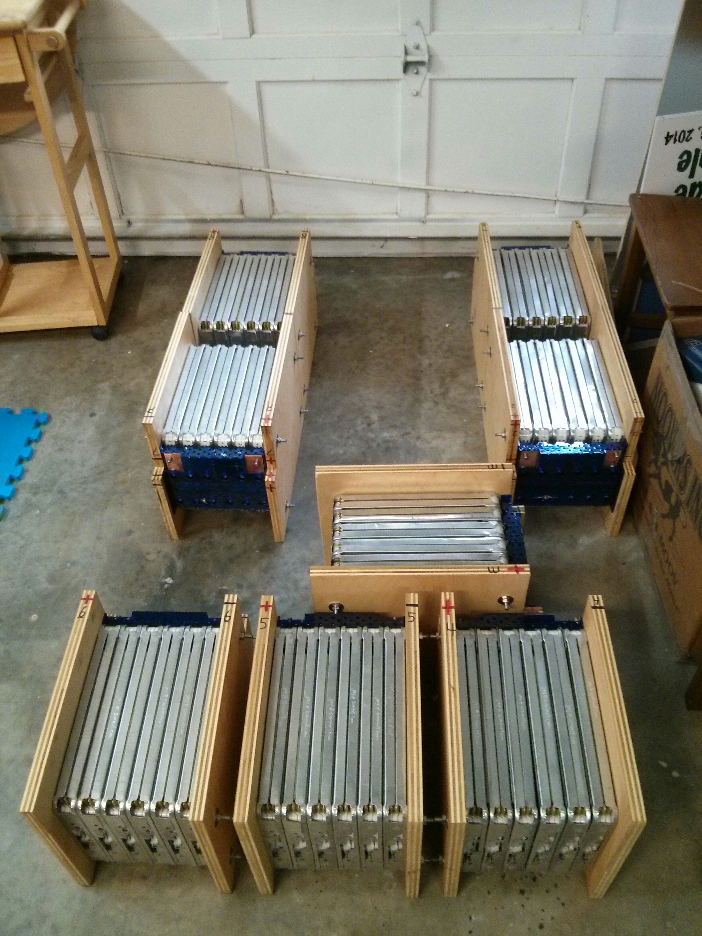
I am building 16 volt batteries using six Nissan Leaf LiIon cell modules. (A Nissan Leaf battery has 48 modules, supplying the construction of 8 of my “batteries”.) My Battery is arranged in a 3P2S (two sets of 3 parallel modules in series), giving a 180 Ah capacity and nominally 16 volts (each module from a Nissan Leaf has 2S2P cells inside, so the module goes up to 8.4 volts maximum at 60AH).
This video (playing at 4x-16x speed) shows all of the work that goes into building a battery. Directions with more information are below.
To build a battery, here are the parts you need:
- Two end plates, made from steel or plywood.
- Six nissan Leaf modules, sandwiched between the end plates.
- Four pieces of threaded rod, 10.5 inches in length, with the following hardware for each rod:
- Two nuts
- Two lock washers
- Two fender washers
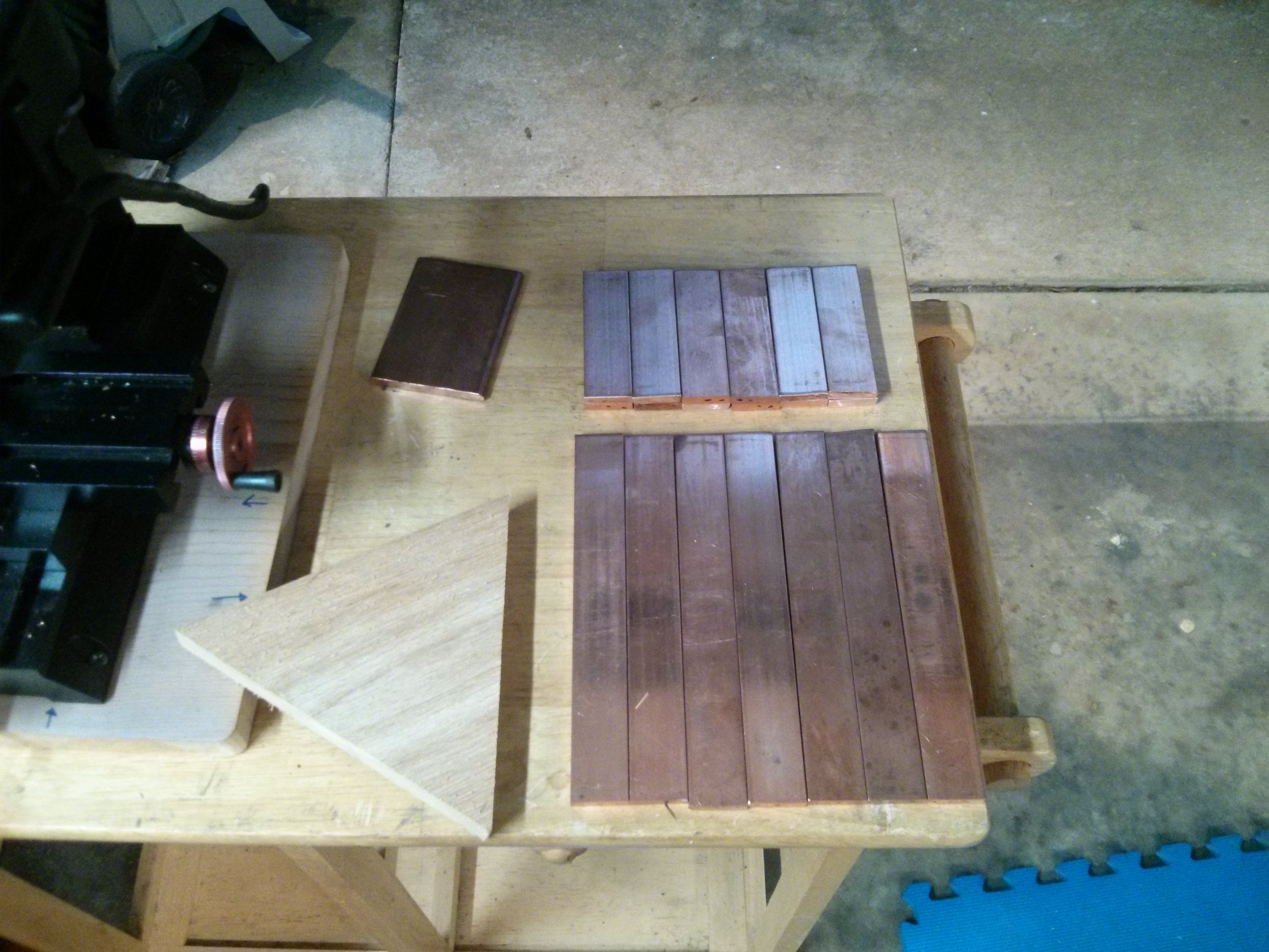
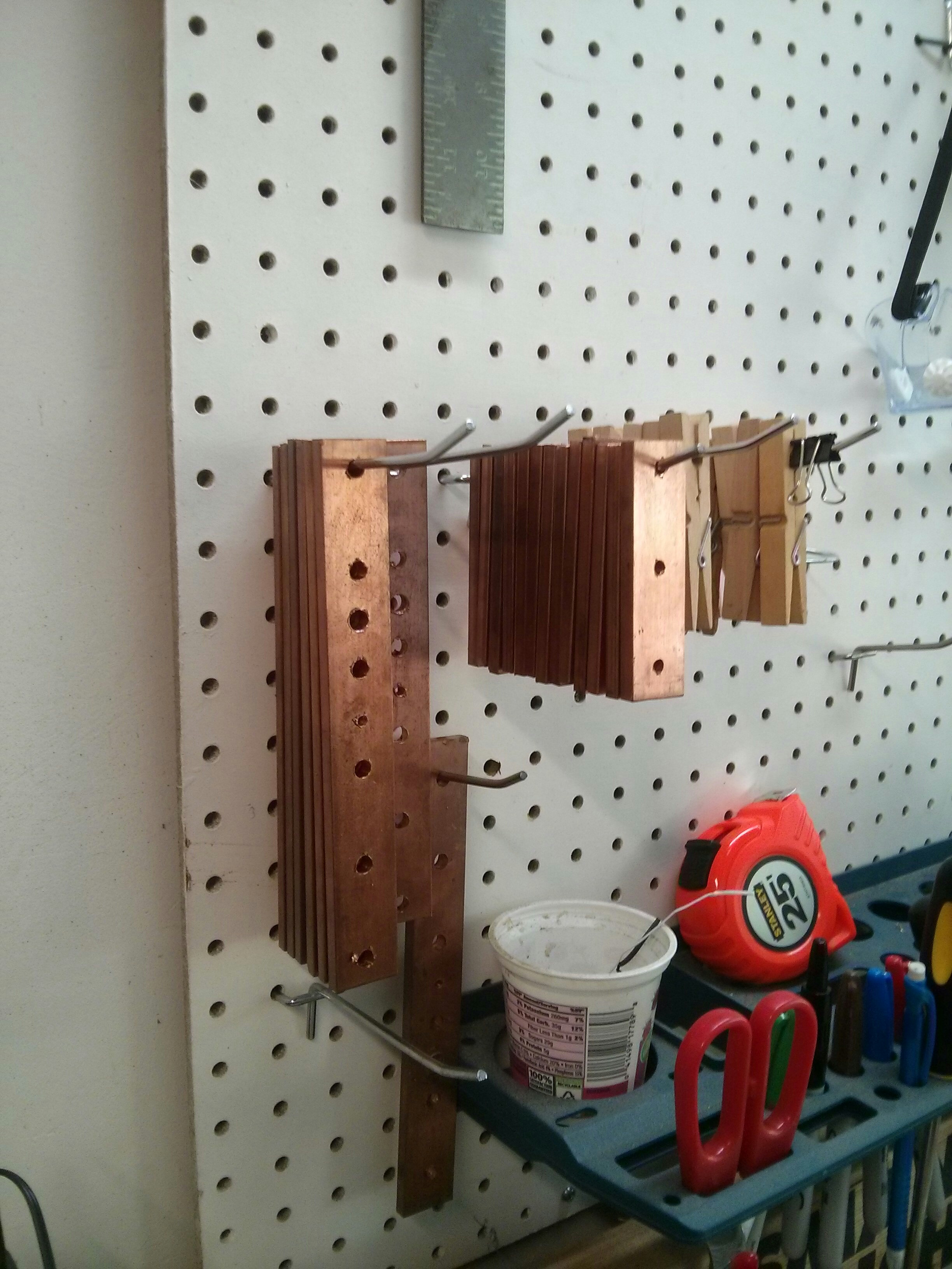
- One 7.5″ x 1″ x 0.25″ copper bus bar (to make the series)
- Two 3.5″ x 1″ copper bus bars (to join the sense terminals) I used 0.25″ thick so that I could source it from the same copper as the series busbar above, but this is overkill, you could use 0.125 or even smaller.
- Two 3.5″ x 2.5″ x 0.25″ copper bus bars (to be the + and – terminals of the main battery).
- 12 M6 bolts (can re-use the ones that came with the leaf modules)
- 12 M6 Locking washers (I used Belleville Spring lock washers)
- six M4x16 machine screws for the sense terminal bus bars
- six M4 locking washers (I used Belleville spring lock washers)
- three M4x8 machine screws for the BMS terminals + 5 more lock washers
- Two 5/16th bolts (1″ or 0.75″) for the + and – terminals. (could substitute 1/4″ or metric bolts, I used 5/16th because that is what golf cart batteries use.)
- (very optional) one more 5/16th bolt for the series bus bar if you want to attach a 5/16 ring terminal from an existing battery monitoring system to each “8 volt” half of your battery.
- 12×12″ acrylic sheet to laser cut battery cover from.
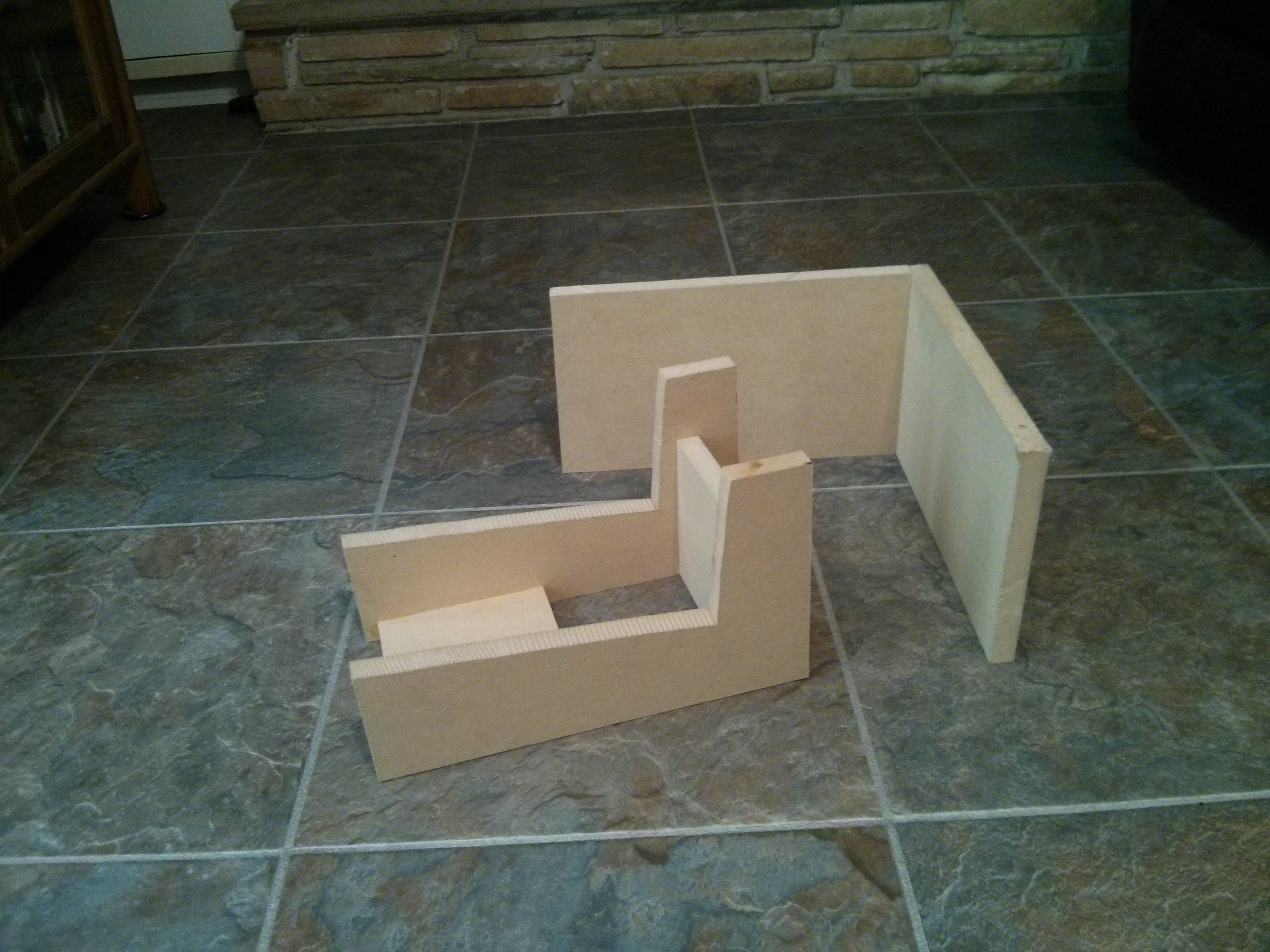
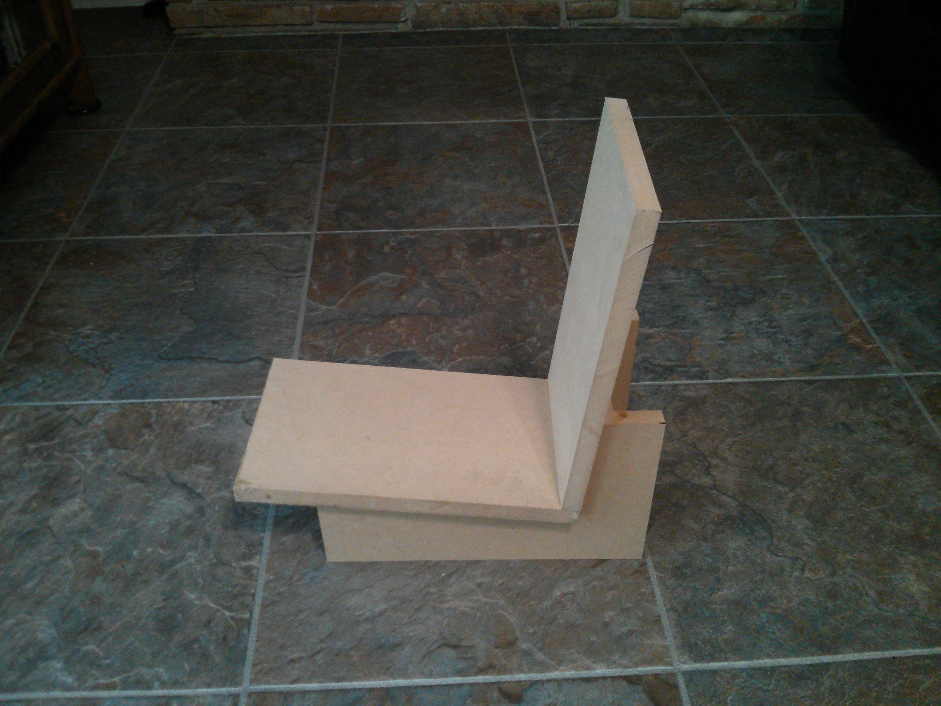
The End Plates
The Nissan Leaf battery pack uses steel end plates, and has 18 of them (except that 16 of them are in “pairs” and need to be cut apart if you want to use them separately.) Also, the 8 “top” ones are smaller than the leaf modules, while the 2 “side” ones and 8 “bottom” ones are slightly larger, but have weird protrusions, making them difficult to use to stand the batteries up on their sides.
I decided to make sixteen uniform plates out of 3/4″ plywood. The largest advantage of plywood is that it is inexpensive, easily shaped, and electrically non-conductive. A non-flammable high-temperature plastic or fiberglass/carbon fiber would be even better, but much more expensive. I coated my plywood plates with polyurethane to give them some water resistance.
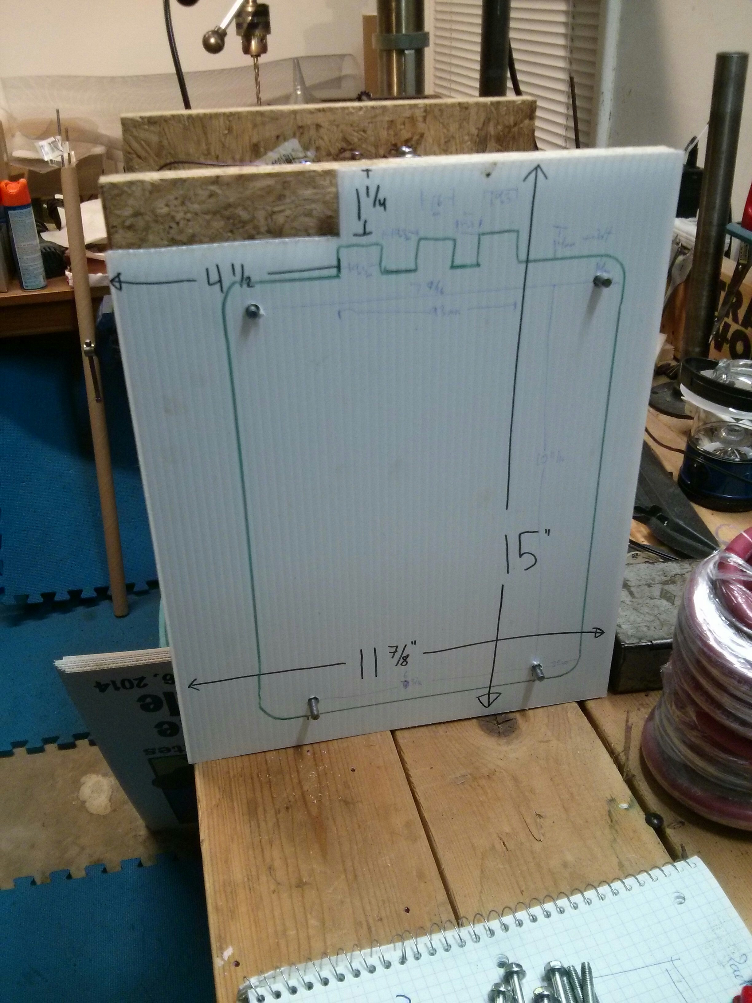
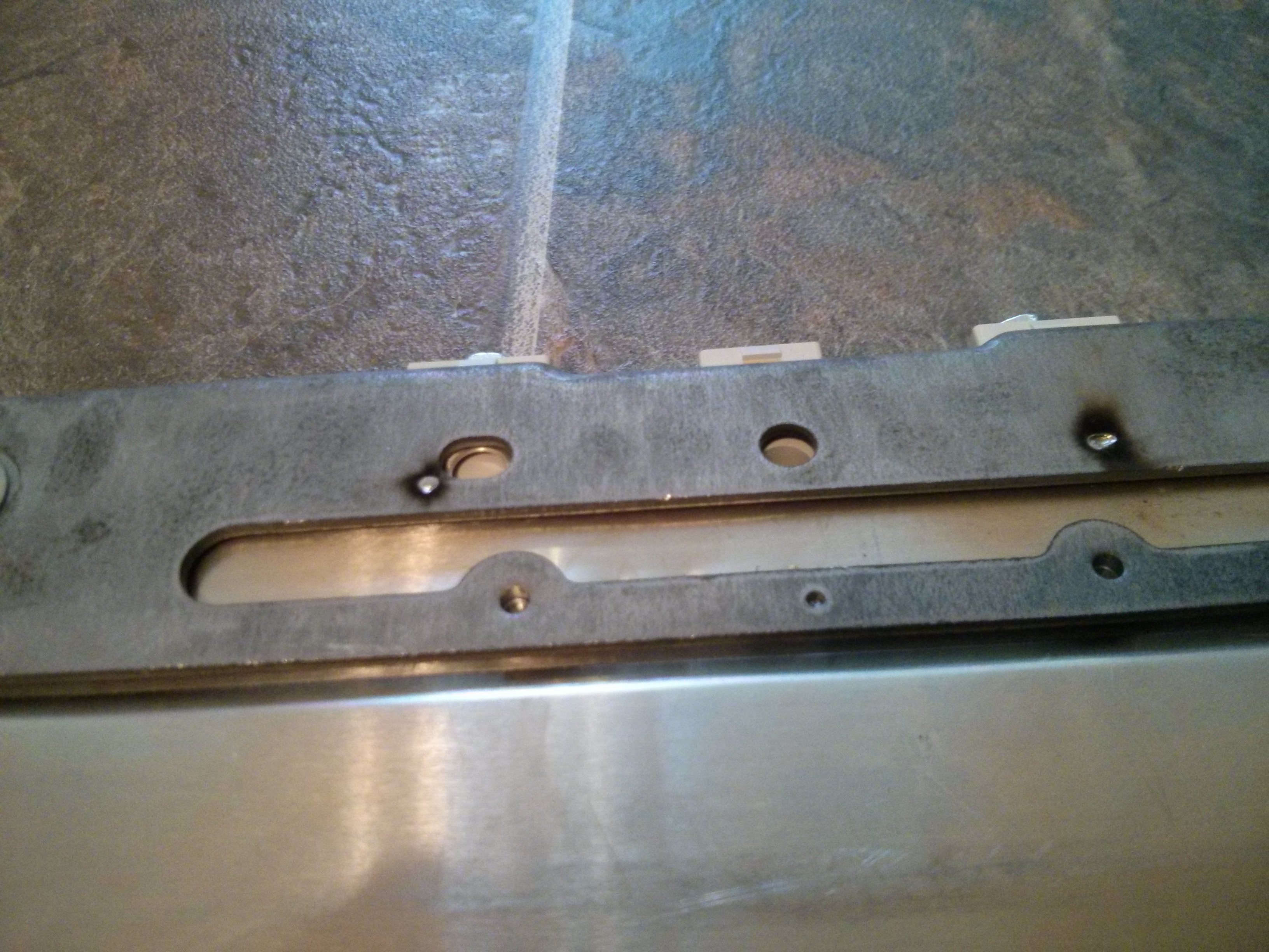
My plates are 11 7/8″ wide by 15″ tall. I place the Nissan leaf modules 1″ from the bottom and one side, which gives me around 1.25″ above the terminals and 2″ above the other side of the module. I used a steel Leaf battery plate to transfer the hole position for the threaded rods. The top rods are approximately 7 9/16″ apart (93mm between the holes) and the top holes are around 14 mm from the top and side of the module. The bottom holes are closer together, with approximately 6 3/16″ between the holes. The bottom holes are around 10mm above the bottom of the leaf module, and 32mm inside from the sides. The vertical distance between the top and bottom holes is approximately 10 11/16″.
I also cut a notch that is 4.5″ by 1.24″ from the corner where my terminals will go. (This is the side with 2″ of clearance.) This notch is optional, but makes it easier to have battery cables going away from the battery to the side.

Physical Assembly
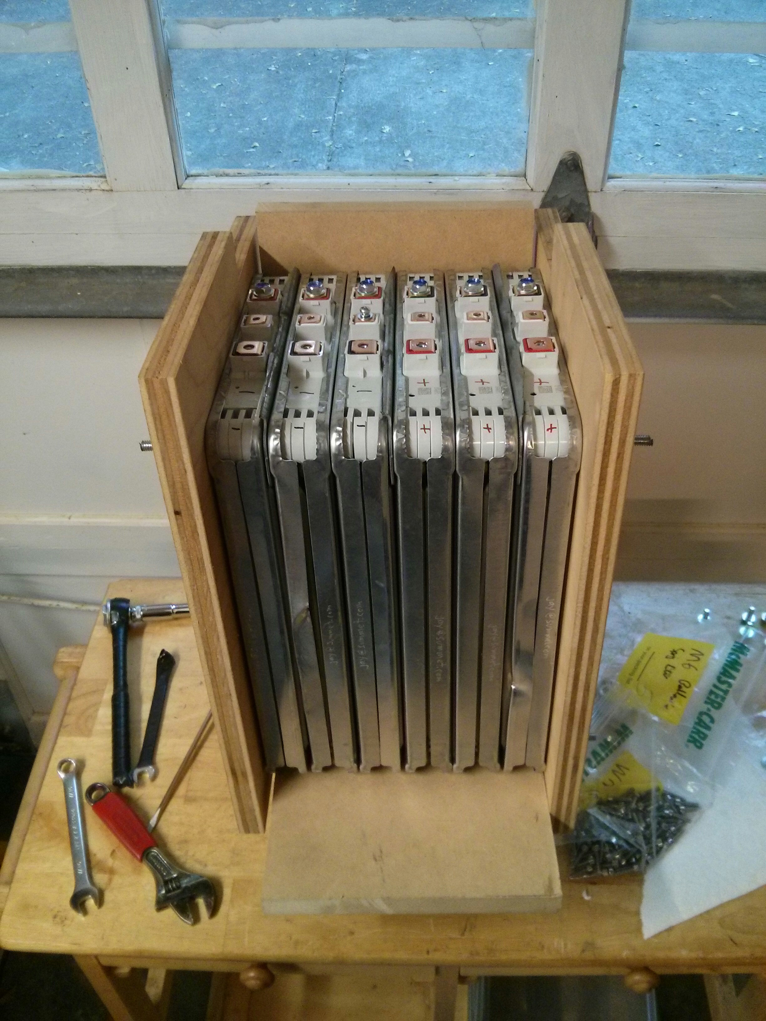
Push the four rods through one end plate, using a fender washer, lock washer, and nut to keep it from falling through. I fashioned a jig to support the six modules evenly while I tightened things up.
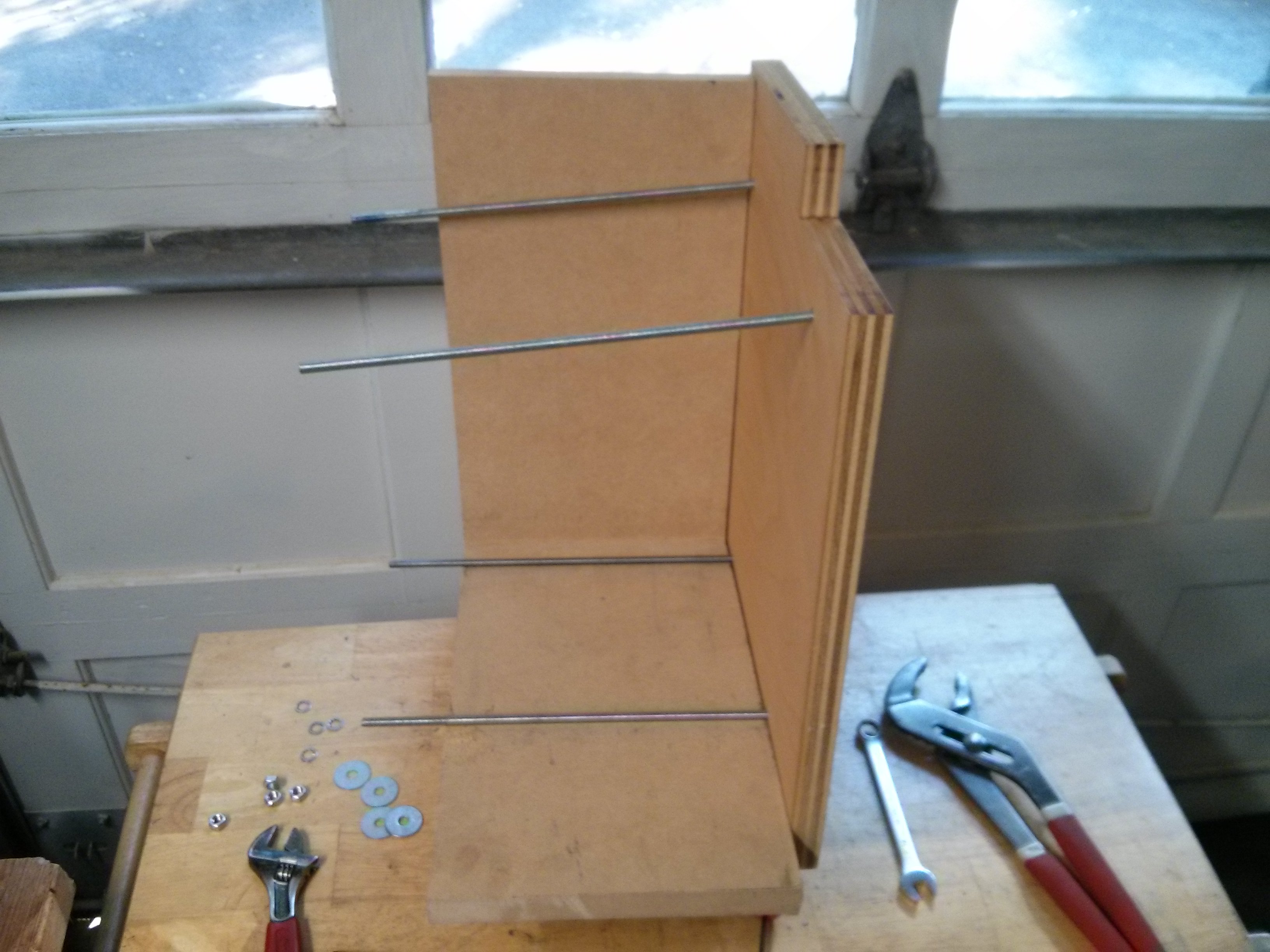
Place three modules on the threaded rod in the same orientation. These will be the three sets of parallel modules. You can choose to have your positive terminal on the left or right side (w.r.t. the notch and wider side) depending upon which way you orient this step. In my situation, I made some one way, and some the other way to make sure my overall battery box layout would be organized appropriately for how my main series loop of battery cable would run. Place the other three modules in the opposite direction.Place a second end plate on the other end of the stack and loosely affix it using a fender washer, lock washer, and nut on each threaded rod.
Now you need to make sure that each battery module is exactly in line vertically and horizontally with the others before you tighten them into place.
If you don’t have a jig, set a flat piece of wood slightly less than 8″ in length, at least a few inches wide, and more than 1″ high on a table, and place the six modules so that they are evenly supported by the wood, allowing the end plates to wiggle around. You may want to use the series busbar to check alignment across all six modules. I used a rubber mallet to tap the end plates and the modules into place.
Tighten up the nuts until the end plates hold themselves up. (You may want to adjust the end plates as far upwards as they will go to maximize the amount of space at the top / terminal side of the battery.) Make sure that all six Leaf modules are exactly the same height now, so that the busbars across the terminals will make contact with each terminal evenly.
Tighten the nuts on the four threaded rods evenly such that the six battery modules are squished together into an 8″ space. (i.e. 8″ exactly between all four corners of the end plates.) When held in compression for proper operation, the leaf modules should be exactly 1.3333 inches in width. (Positioning the center of the terminal posts exactly 1.3333 inches apart.) This compression keeps the cells inside from swelling when discharging or charging, and prolongs the battery life.
Battery Safety
You must be VERY careful to NOT short out the leaf modules. Ways to do this include dropping a non-insulated wrench, screwdriver, bolt, not, etc across the terminals, accidentally dropping a busbar across the wrong terminals, or placing a metal tape measure across the wrong set of terminals.
Also, don’t stack more than one module vertically against a chair. If the stack slides down, one battery module’s bolts may touch the side of another battery module and cause sparks to fly and spot weld bolts to steel, which is more excitement than you want to deal with.
I strongly recommend wrapping the handles and shaft of any tools you will be using with electrical tape if you are not using electrically insulated tools specifically designed for busbar/electrical work. I also recommend keeping the top of the battery covered with a plastic or rubber sheet when not actively working on it, and building guards for the top of the battery when you are done. The LiIon modules are rated at 60 AH each, but can discharge at a MUCH higher rate, easily producing hundreds of amps into a short. Even half of a module at 4.2 volts can cause impressive sparks due to the high amperage, and if you were to short the full series set of 16 volts, it can deliver 8000 watts (8kW) for a short period of time. This is more power than a household clothes dryer or range, and will easily weld (or melt) metal and provide much more excitement than you want to experience. It can of course also cause injury or death.
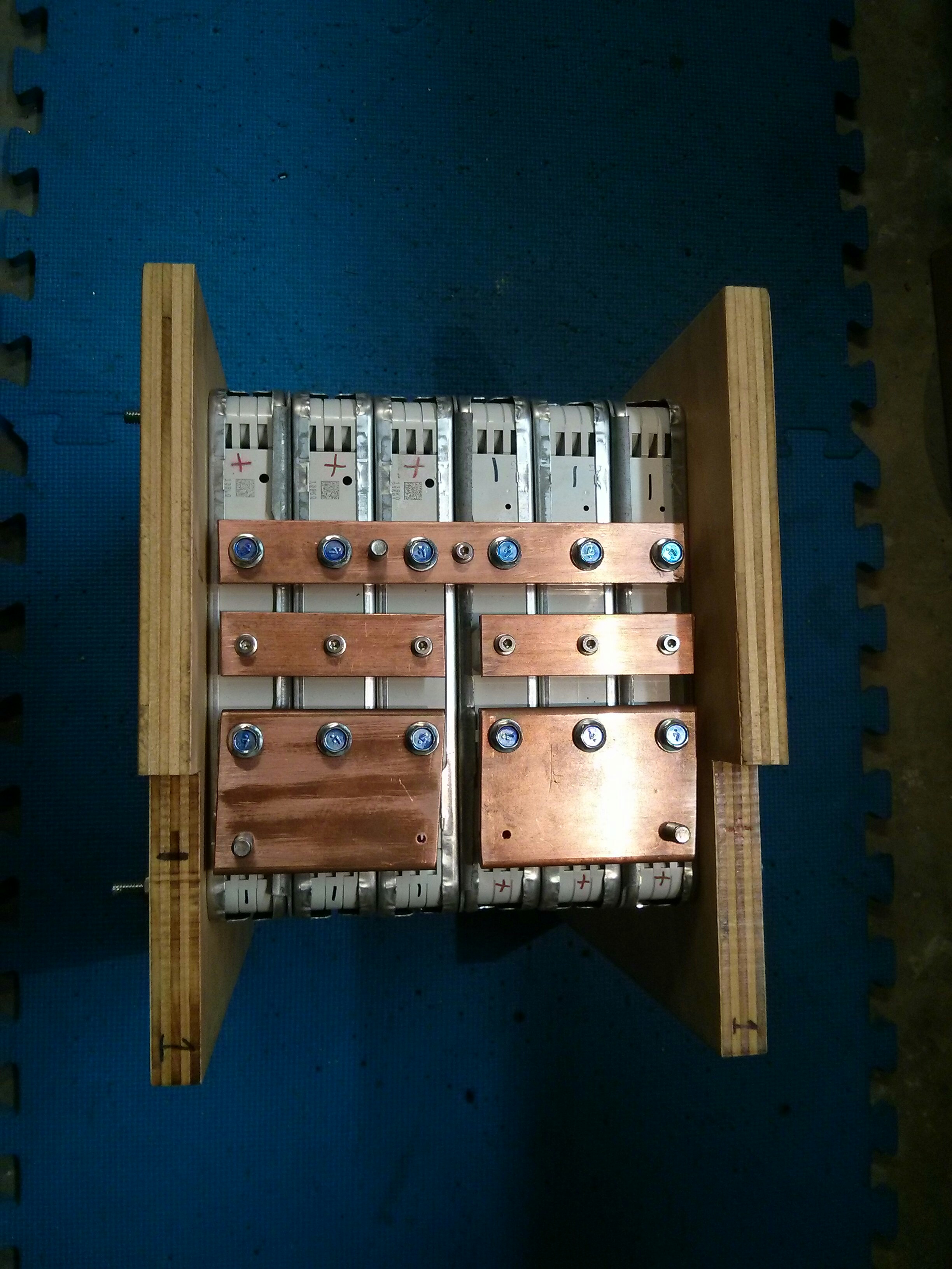
Series busbar
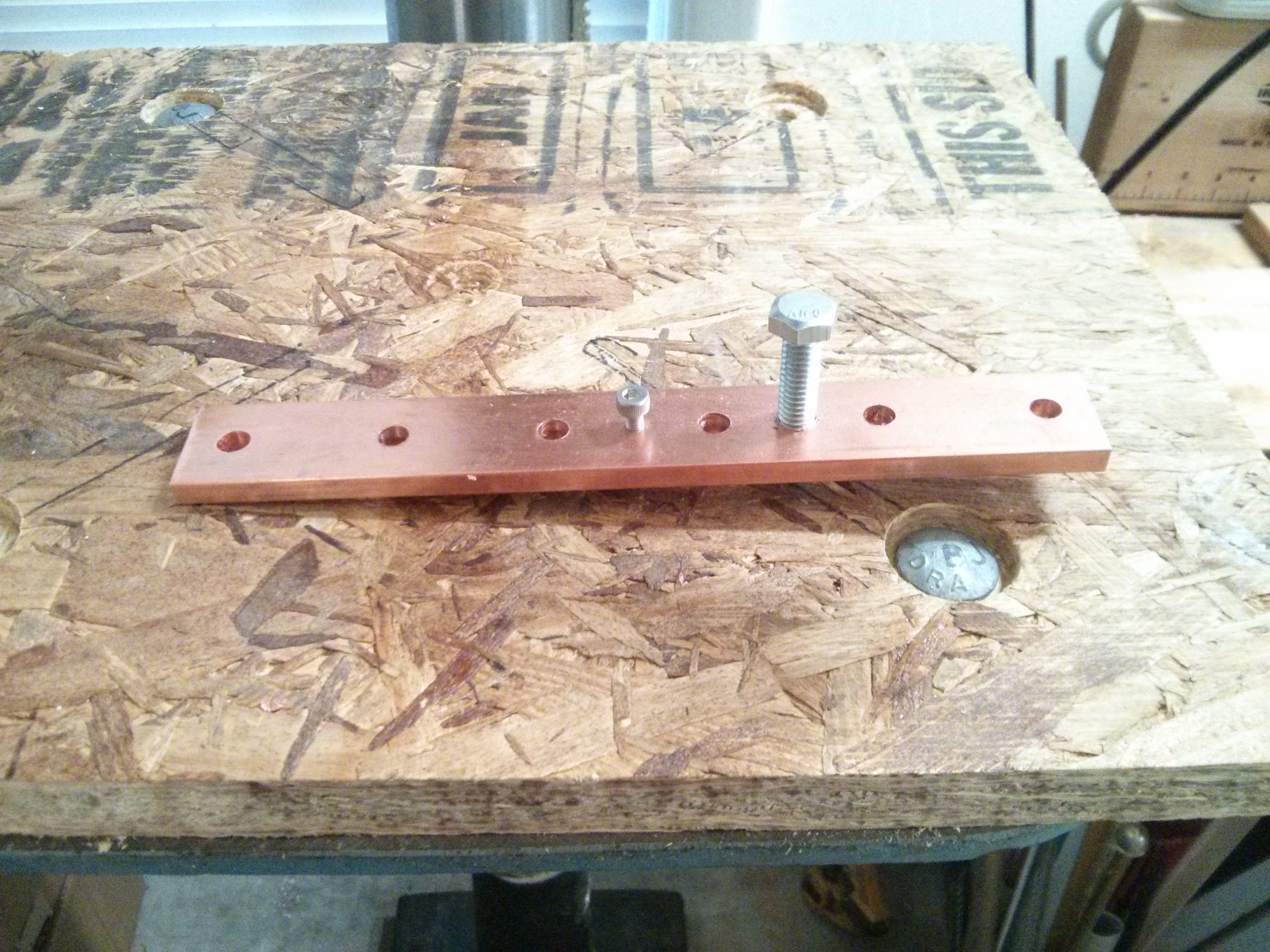
The series busbar connects three modules in parallel, and then bridges across to the other three modules, connecting them in parallel and the two sets in series. It is the longest busbar, at 7.5″ in length. I made mine out of 1″ wide x 0.25″ thick copper busbar, sized to carry my 75-100 amp continuous and 500A absolute peak loads. This busbar is 0.25 square inches in area, and has 32.9 microhms (0.000329 Ohms) of resistance per foot. The DC ampacity of this size of busbar is 403 Amps, giving me a comfortable safety margin. You could probably safely substitute a 1″ by 1/8″ busbar (rated at 271 Amps), or even a 3/4″ by 1/8″ (rated at 212 amps), although they would have higher resistance and waste more power as heat.
This busbar has six holes spaced 1.3333 inches apart for the M6 bolts to attach it to the terminals on the leaf modules. I used 1/4″ holes which gives a small amount of wiggle room for the bolts. I started the first hole 0.416″ from the edge, and then drilled each additional hole 1.3333″ farther along, leaving another 0.416″ from the far edge. I also drilled a 9/64th hole and tapped it for an M4 screw to use as an attachment point for my BMS system in the exact center of the busbar (halfway between the 1.3333″ spaced holes). One extra feature I added was an additional hole drilled at 17/64 and tapped for a 5/16-18 bolt also halfway between two 1.3333″ spaced holes. This bolt is the size of my previous golf cart battery terminals, and the only point of it is to attach my current battery monitoring system to the module here. [My current battery monitoring system is designed for 6v or 8v golf cart batteries. So I will be attaching it at the + and – terminals, but also at this center point in the battery, so each 16v battery will appear to be two 8 volt golf cart batteries to my PakTrakr system.] The head of the 5/16 bolt fits EXACTLY between the two terminals of the leaf battery, if you turn it so that the flat sides are even with the terminal blocks. AND, if the hole is exactly 0.666 inches from each of the 1.3333″ spaced holes (which are 1333 mills apart).
FYI- Each turn of my X knob on my Sherline Mill gives 50 mills, so 26 turns + 30 mills gives a 1.33333″ spacing, and 13 turns + 16 mills gives 0.666″ spacing +/- 10 mills should be fine. Unless you need to attach a pre-existing 5/16″ ring terminal to the middle of your battery, I’d suggest leaving this step out.
Note: If you are not lucky enough to have access to a mill, you can get similar accuracy by using a paper printout with a center-punch to mark where to drill your holes.
When installing this busbar, I recommend having the two end bolts in the busbar, lifting it onto the modules, and screwing the two bolts down. This will keep the busbar from sliding around while you place the other four bolts into it. Don’t drop any bolts.
Sense Terminal parallel busbar
The Nissan Leaf module is actually made up of a 2P2S set of pouch cells, where each pouch cells is 4.2 volts and 30 AH. So four of them make up a module, giving 8.4 volts maximum and 60 Ah. To make sure that the cells that make up the module do not go out of balance, Nissan exposes the center of the 2S arrangement as the third (middle) sense terminal. These sense terminals are slightly smaller (16mm vs 19.3mm) than the “power” terminals on the module. Because we are putting three modules in parallel, we need to put the sense terminals in parallel as well. Unless something goes seriously wrong, their should not be many amps going between the different parallel modules, so I could have used much smaller busbars (or even wire!) to parallelize these sense terminals. However, I already had a lot of 1″ x 0.25″ busbar, so I decided to make my sense terminal busbar out of the same material. I would suggest using 0.75″ wide busbar if you have not already purchased your copper, as that would give more room between the busbars on top of the battery. And you could easily go down to 1/8″ to save cost and weight.
It is 3.5″ in length, and has three holes for the M4 machine screws that connect to the sense terminals with their centers spaced 1.3333″ apart. I used 3/16″ holes. There is 0.416″ on each end, which is 416 mills, or 8 turns of 50 milles + 16 mills on my mill.
I also placed one more 9/64th hole 0.6666″ between the 1.333 spaced holes that I then tapped for an M4 screw to be used by the battery BMS system (discussed below).
Each battery will use two of these parallel bars, one on each of the 3 parallel modules. Be very careful to only bridge the sense terminals for the three modules on each end, as if you bridge the center point on the battery with the series bus bar in place, you will cause a short! It may be safer to install the short busbars first (creating two 8 volt battery halves that are separate), and finally joining them as your last step with the longer series busbar.
+ and – Terminal busbar
The positive and negative end of the battery are on the same side (with the notches in the end plate). Which is positive and which is negative (left or right) will depend upon the order in which you stacked the Leaf modules. I recommend that you mark the polarity in several different ways. Etch a + or – into the terminal busbar, coat it with red or black tool dip or electrical tape, and also spray paint the notch area of the end plate red or black, possibly with a + or – stencil.
Because I wanted room to attach a relatively large 00 welding cable 5/16″ ring terminal, I used a 3.5″ x 2.5″ copper busbar for the terminals, allowing me to have two rows of holes. The first row of holes is approximately 0.5 to 0.6″ from the edge, and has three evenly spaced 1.3333 holes drilled at 1/4″ which connects to the leaf modules. I also marked three 1.33333 spaced holes on the other side, but only drilled out two of them. One of them I drilled using a 17/64 drill and tapped for a 5/16-18 bolt to act as my main terminal. The other I drilled using a 9/64 drill and taped for an M4 screw that will connect to the battery BMS system.
If you will be running cables to the left or right, you may want to place the 5/16 terminal closest to the end plate. If you will be running a cable to another battery that is sitting face-to-face with the current one, you may want to offset the 5/16 terminals so that they are farther apart in your battery box.
BMS system
I am using Mini-BMS boards for my BMS system. The version I purchased has one small board for each cell. My battery has 4 “cells”, each of 4.2 volts. The first is between the negative terminal and the sense terminal/bussbar on the first parallel set of 3 modules. The second is between the sense terminal/bussbar and the series bussbar. The third is on the second set of parallel modules, and is from the series bussbar to the other sense terminal/ bussbar. The forth is between the sense terminal/bussbar and the positive terminal of the main battery. (Of course, each module has two cells in each position, so my “cell” is really made up of a parallel arrangement of six cells, two per module in my groups of 3 parallel modles. Because all six pouch cells are held in parallel due to the parallel nature of my groups of 3 modules, one BMS board will provide protection for each set of six cells. (So in total, my Battery has six modules, and 24 actual pouch cells, four per module.)
I should have purchased the version of the mini-BMS board that supports 4 cells per board, but at the time I purchased them I wasn’t sure I would be making batteries that would be “4 cells” in total. I can simply connect together the + and – terminals of my four cells with wire and connect them to the appropriate place on my full Battery. I have also daisy chained the “alarm” circuit from each of the BMS boards, and I will have to jumper this over to the previous and next battery once I wire up the entire power system.
Each BMS board can dissipate up to half an amp of current if it detects that one cell is getting charged to a slightly higher voltage than it’s neighbors, working to bring the pack as a whole into alignment. However, the primary role of the BMS boards is to sound the alarm if any individual cell voltage goes too high (overcharging) or too low (over discharging). In the “too-high” situation, it will turn off the charger automatically. In the “too-low” situation, it will buzz an alarm to alert the driver to quit discharging the cells, and possibly reduce the total throttle range to put the truck into a “turtle” mode.
Electrical Shielding
Because the Nissan leaf modules have the terminals relatively close together at the top the spacing between busbars is not terribly large. It is more than far enough for the relatively low voltages (4, 8 or 16 volts maximum) to suppress any arc that were to form, but it would be easily bridged by a falling bolt, washer, screwdriver, wrench, etc. Because of this, I have fashioned electrically insulating covers for the batteries that attempt to only expose the actual terminals to reduce the risk of accidental shorts. The current generation of protective covers is laser cut acrylic stock. Arguably, craft plywood would be less brittle, but I do not expect these covers to have to withstand harsh shocks, as they are within the extents of the 3/4″ plywood end pieces. They are mostly to keep a falling screwdriver, wrench, or bolt from causing a lot of excitement.
You can find more information about the battery covers (with design files) at this post.
Weight
The entire battery unit, with BMS weighs 58.6 lbs. Eight of these units will be replacing 20 lead acid golf cart batteries (also weighing 60 lbs each), dropping the battery pack weight from 1200 lbs to 480 lbs, which is a 60% weight savings.


 information")
Great video and great video format! Feels weird to commend it, but I also like your appropriate use of safety equipment.
It never hurts to keep your eyeballs ;>
Pingback: 16 volt Nissan Leaf Battery Management System (BMS) information | Jay's Technical Talk
Pingback: Current imbalance with dual chargers – TSM 2500 / EVCC | Jay's Technical Talk
How about vacuum formed ABS for the plastic shields? One piece for the main cover and if you want barrier strips between the bus bars, form a bunch at once that can be cut out to make L shape strips. Set the strips between the bars, apply some ABS cement then press on the main cover.
Quicker to make than laser cutting and gluing together multiple pieces of acrylic sheet, plus you get to build a vacuum former. 🙂
Yes, that would also be a good option, especially if I wanted to make a lot of them. I had easier access to a laser cutter than a vacuum former, so went with the laser cut option. ABS could also be more durable than acrylic, depending upon thickness, although so far the acrylic covers have held up just fine.
Hi, great videos! I am wanting to do something similar but on a much smaller scale,lol. I was thinking of using just 2 modules to make a battery for my kayak. So I’m thinking those would be in parrallel and I could use one of the BMS boards you thought about using? Any suggestions or help is appreciated! I was going to get the 2 modules from eBay unless you know of a better place?
Two modules in parallel would only be 8 volts, if you put them in series you’d get 16 volts, better for a trolling motor. There are a lot of BMS solutions for a 4S pack like that (or a 2S if you really do want 8 volts) on Ebay, just make sure they support 4.2v cells (instead of the 3.7v that is more common for 18650 sized modules).
Hello, Excellent project and video. I have a vacation home which is totally off the grid and I and thinking of building your system using Leaf batteries. I have enough skills and knowledge to handle most of the project, however, the challenging part for me is making the copper bus bars. I am not a machinist nor to I have the machining tools that you use. I see the specs and tolerances are pretty tight, so not much room for sloppy cutting and drilling. What do you recommend?
See my post on achieving similar accuracy with a paper template & center punch:
https://www.summet.com/blog/2015/11/12/rivaling-mill-accuracy-with-a-printed-template-and-centerpunch/
You can easily get tolerances good enough with a few simple tools (printer, center punch, hammer & drill – having a drill press helps a lot). If in doubt, make the holes a little large, so that your bolts can slide around a bit inside the hole.
I see this over a year ago now but I’ll try anyway. Thanks for making and sharing such a detailed build. I was thinking of going with 32 volts and 8S but I’ve been warned it might be better to do 7S with my 24 volt solar energy backup system. The migraines have been bad and I’m having a hard time figuring out how I would do the bus bars and electrical arrangement of the modules into packs??. I have 28 of the 8 volt leaf modules. I’m not happy about wasting, leaving out, half a module on each pack to do 7S . Any suggestions are greatly appreciated. Making the templates and bus bars I can do once I have a electrical design. It’s figuring the electrical layout of the packs that’s giving me huge headaches. Thanks
I can tell you that 6S is a little bit too low voltage for many “24v” inverters that are designed for Lead Acid batteries. A “24v” lead acid battery has 12 cells, that range from 2.26vpc down to 1.7vpc, or 27v at fully charged down to 20.4 volts when close to empty. A 6S pack of the Leaf modules is 25.2 at absolutely fully charged to the manufacturers absolute max spec, but drops down below 20 volts when empty. In my experiance, one inverter (from PowerJack) has problems running loads when the input voltage goes below 24 volts, meaning that most of your pack capacity isn’t usable.
However, the Leaf Modules are not great for putting into 7S configuration. In addition to the fact that you are just leaving half of the last module “unused” the middle “sense” terminals are NOT designed to have a large amount of current pulled or pushed through them, so I would be worried about melting something internal to the module at that point.
If your inverter can handle the upper voltage (33.6volts) I think an 8S would be better than a 6S. Perhaps if you only charge your cells to 4.0 or 4.1vpc the inverter would be fine with a maximum voltage of 32 or 32.8 volts.
(I build a 6S pack and it works, but I’m having issues at the lower end of the voltage range with the specific inverter I’m using….)
See:
https://www.summet.com/blog/2019/02/06/running-our-240-volt-well-pump-in-a-power-outage/
Pingback: Running our 240 volt Well Pump in a power outage | Jay's Technical Talk
Pingback: Automated Balance Charging & Capacity testing Nissan Leaf Modules | Jay's Technical Talk