The last hurricane knocked out our electricity for 3.5 days. (Other people in our neighborhood were without power for 6+ days). I have a 120 volt inverter that I used to power our fridge, microwave and internet, but our well pump requires 240 volts. It was really annoying to have to transfer water from our tub to the toilet tank to flush, and not be able to wash our hands at the sink or get water from the tap when we wanted to.
My wife has given me a $1,000 budget to expand our backup system so that we can run the well pump in power outages, and the first step is to figure out the actual power draw of the well pump.
The pump is powered off of a 20 amp circuit, so the maximum draw is 240v * 20A = 4,800 watts. I measured the actual continuous draw when the pump is running at just under 10 amps, or 10 * 240 = 2,400 watts continuous. I will probably need to purchase an inverter with a surge rating of twice that to support the inductive surge the pump motor is likely to draw when it first turns on.
I hooked up an energy monitor to the pump circuit and monitored it for a few weeks. The energy monitor estimates that the well pump uses between 6-8 kWh of power over the course of a month, so I will only need 1-2 kWh of battery capacity to be able to run it for several days.
Battery Selection
I decided that although there are a lot of advantages to sticking with a 12 volt system (wide selection of chargers/inverters, lots of 12v accessories, easy charging from auto systems), the fact that I was going to be building a relatively high power system (with an inverter able to continuously drive 2,500 watts and intermittently go a lot higher) meant that I needed a higher voltage battery so that the amount of amps going through my battery wiring and inverter was kept at a reasonable level. Although my electric truck regularly has peak power draws of up to 500 amps, it uses 00 welding wire to handle that. I also decided that although you can generate high power output from a 12 volt input, I wanted to buy an inverter that was designed by somebody to take advantage of a higher voltage supply.
For anybody following along, for an occasional use backup power system, I still think that lead acid golf cart batteries are a great choice. Although they are old technology, and limited to only 300-500 cycles, if you are only using them in power outages (as opposed to powering your off grid house every day) it is hard to beat the cost advantages of a flooded lead acid golf cart battery.
However, because I want my battery to be dual usage (powering a boat when not preparing for a hurricane), weight was also a factor for me. And due to my experience converting my electric S-10 truck from lead acid batteries to use Nissan Leaf modules, I have a lot of experience in taking used Nissan Leaf battery modules and making use of them. Because they are used, the actual cost is almost comparable to new golf cart batteries, but they do introduce complexity due to their need for a BMS system in unattended usage scenarios.
Inverter Selection
After doing a lot of research, I decided that the best bet for a sub $400 inverter to power my well pump was the PowerJack 8000W model. Like all Chinese inverters sold in this price range on eBay, the 8,000 watt specification is completely suspect, but I am hopeful that due to it’s low frequency nature, it will be able to start up and run my 2,500 watt well pump. The 2,500 watt draw is intermittent, giving the MOSFETS and transformer a lot of time to cool off between runs. We’ll find out soon enough…..
Building the Battery
I used the same basic battery construction method as for the eight batteries I made for my S-10 Truck conversion, but instead of making them 3P2S for 16 volts at 180 AH, I made it 2P3S for 24V at 120 AH. If you want to download the templates I used for the holes in the bus-bars you can download the PDF file here: BusBars.pdf. I used 1/4″ holes for the M6 bolts on the Leaf Modules, 9/16th holes to tap for a M4 socket head cap screw for the sense terminals, and 17/64th holes to tap for a 5/16th bolt mounted from the underside for the terminal lugs.
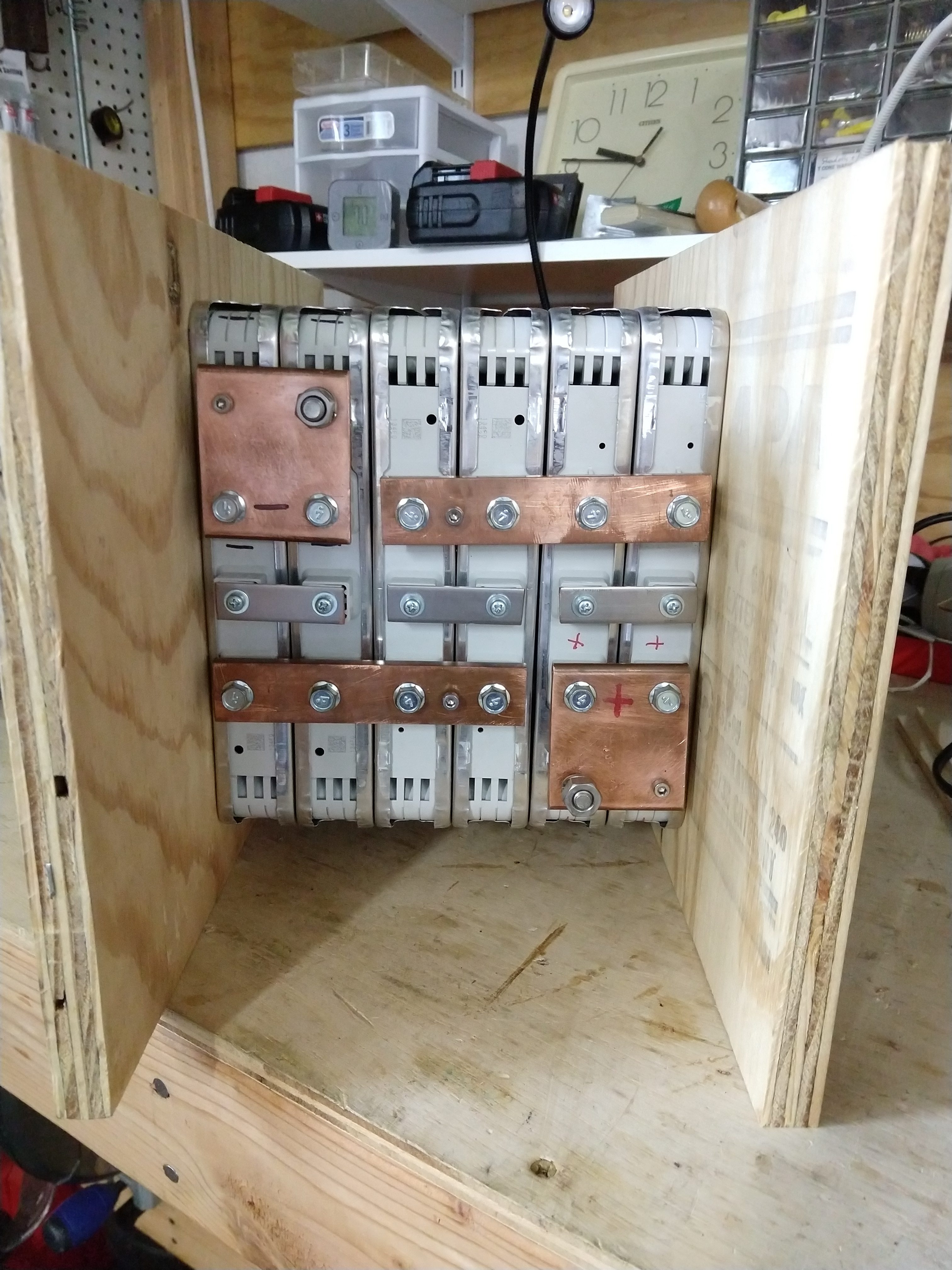
In this next video, I show all of the circuit breakers, cell voltage sensing leads, meter, connectors and pre-charge circuit that I added to the above physical battery to make it safer and easier to use.
Power Jack Inverter
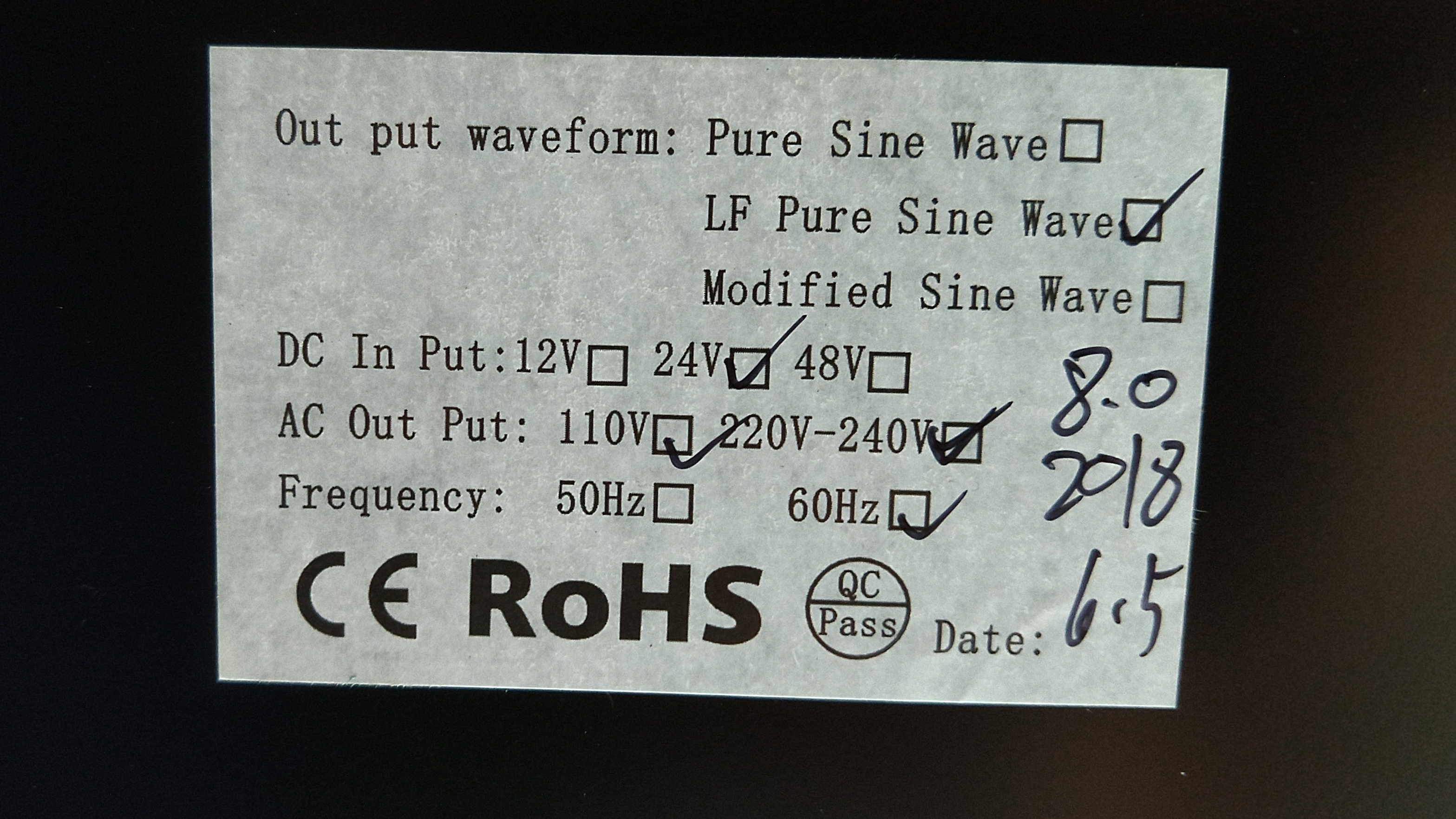
I had to repair part of my Power Jack inverter straight out of the box (They shipped me the parts under warranty in 7 days). After replacing a MOSFET board that was lacking an indicator light, I tested it out with various 120v appliances around the house, and found that it was a quite capable inverter and was able to power everything that I would normally plug into a 15 amp household outlet. The video above shows how to open up the case, do the MOSFET replacement and the tests I performed. Here is the sticker from the bottom of my inverter:
Low Voltage Issues
The inverter powered the well pump just fine as long as the input voltage was at the upper end of that provided by my LiIon battery (24-25 volts). There would be a very brief initial current surge when the motor started up (well under a second, not easily detectable by the slow averaging meters), but it would drop to an average load of 2000 watts (85 amps at 24 volts) for the remainder of the 30-45 second pump runtime.
However, as soon as the battery pack started to be depleted and the input voltage started to drop into the 22-23 volt range under load, the well pump would no longer start up (even though the battery was sourcing 200+ amps / 5,000+ watts to the inverter for multiple seconds before the 200 amp circuit breaker would kick in). I suspect if I had a 7S battery pack (instead of the 6S I currently have) the higher voltage would allow the inverter to start the well pump for a lot more of the pack capacity.
But, as I was always planning on “topping up” this smaller battery pack from my trucks 24kWh pack (at 130 volts DC), I don’t think that this will be a showstopping issue. I can keep the small battery pack charged up in the 24-25 volt range, and use it to provide the high current surges (200 amp startup, 85 amp running) for the intermittent usages such as the well pump, while constantly replenishing it with a 20 amp input from the MeanWell SD-500-24 converter that I’ll be using to charge it.
Charger Hardware
I cut out some plywood to make an enclosure for the power supply and wired up connections that allow me to power it from my trucks’ battery pack. I have a 15 amp DC rated fuse on the line from the truck, and I’m relying on the 40 amp circuit breaker in the battery for the output side protection, as the XT60 connector is wired right to the power supply. Unfortunately, this is a power supply, and not a battery charger, so it refuses to push 23 amps continuously, and if it detects a high amp draw (above it’s 21 amp limit) it will shut itself down after a few seconds. (Requiring one to remove input power and re-apply to reset the power supply). So while I can use it to keep the battery topped up (or even charged if I’m willing to babysit the voltage output level as the battery gains charge), it will automatically shut itself off if the voltage level on the battery drops a half volt or more such that more than 23 amps are drawn from the power supply.
The solution to this is a current limiting device between the power supply and the battery, which allows current to flow as long as it is lower than 20 amps, but puts a limit on the upper bound of current that can be drawn (for example, when the inverter draws 80-300 amps to start up and run the well pump).
There are several ways to do this: 1. Tie into the existing current limiting/sensing and voltage regulation circuitry in the power supply. 2. Introduce a PWM current limiter between the PS and battery. 3. Introduce some resistance between the power supply and battery to limit the current flow. Option 3 is the easiest, but also the most inefficient, as it may waste a lot of power. Option 1 may require the most work (in reverse engineering the PS) and it voids my warranty. Option 2 is nicely self contained, but does required building a whole new device.
I have a unique situation in that I only need the power supply to “top up” the battery, so that most of the time, the difference in voltage between the power supply and battery will be very small, so only a small amount of current will flow between them.
I’m going to take advantage of a passive variable resistor device that has relatively low resistance when the voltage difference across it is low, and increasing resistance (up to 4-5 times as much) as the voltage difference across it raises. In this way, when the battery voltage is close to the charger voltage, it will waste little power, but when the inverter turns on and the battery voltage sages, the higher resistance will limit the total amp draw to under 20 amps, which the charger can provide. As an added side benefit, these devices act as an indicator that shows when they are limiting current. The only downside to these devices is that they come in certain fixed voltage / resistance configurations, so to get the specific resistance I need I will need to put multiple in parallel.
(In case you haven’t figured it out yet: They are light bulbs…)
Current Limiting between power supply and battery
I tested out both a set of metallic resistors (automotive lightbulbs) and an inexpensive CC/CV step down power supply I purchased on Ebay, and found that the lightbulbs actually had smaller losses overall. I also determined that just to idle my inverter for 24 hours running 30 watts of DSL modem/wifi router would take 2.3 kWh of power. [I only plan on running the inverter for 4-6 hours a day to run the well pump, microwave and let the fridge cool back down.] In a medium load situation (900 watt continuous draw) my whole system has a 71% efficiency (1,800 watt hours provided to the load, 2,510 watt hours to recharge the system) which is quite good considering I’m going through two different batteries (my truck and the smaller one) and two different chargers (trucks charger and power supply) plus the PowerJack inverter.
For anybody wondering, if you wire up five H4 auto lightbulbs in parallel (with high & low beam elements also in parallel), here is the resistance, voltage drop and watts lost to heat/light at various different amperage levels:
1 amp  - 0.016 volt drop  =  0.016 watt  = 0.016 Ohm

12 amps - 0.329 volt drop = 3.948 watt  = 0.027 Ohm

17 amps - 0.879 volt drop = 14.94 watt  = 0.051 Ohm

19 amps - 1.030 volt drop  = 19.57 watt  = 0.054 Ohm

20 amps - 1.37  volt drop =  27.40 watt  = 0.068 Ohm
AC Charging Solution
Because I sold the S-10 pickup truck, I no longer have a 120 volt battery pack sitting in my driveway. But, we have a PHEV and an EV with sizable battery packs that can re-charge their 12 volt accessory battery. So my new hurricane backup power supply will be a 12 volt inverter ran off of the car’s batteries. To use this to top up the well pump battery pack, I’m switching the hardware over to a MeanWell HLG-480H-24A constant current constant voltage LED light driver. (for BIG LED lights, like in streetlights….)
This power supply is basically perfect for my needs, as I can dial in a specific voltage (24.6 volts in my case, which is 4.1 volts per cell) and it will put 20 amps into the batteries as long as they accept it but limit the maximum voltage to the set point. Because it is a constant current power supply, it also does not suffer from the “over current shutoff” that the DC 2 DC power supply had, meaning I no longer need the pile of incandescent light-bulbs as a current limiter. It’s nice when off the shelf hardware will do exactly what you want. Note that this is a good charger, but it does not have a BMS built in. I have a separate balancing charger, as well as a cell balancing circuit board that I use to make sure that none of the cells in my battery get out of balance. But if you wanted to use a system like this unattended, you would need a true BMS that could shut down the charger if any cell voltage got above 4.2 volts (and the well pump inverter if any cell voltage got too low….)


Hi Jay, I recently received one these Powerjack inverters, And upon inspection I also found some issues. It was supposed to be 240V split phase, but there was no neutral wire connected to the Terminal strip. the 120 volt plug and terminals did not have power. I opened it up and found wire ends that had simply slipped out of the terminals because they were badly crimped. I also believe the wires from the transformer were incorrectly connected. Could you possibly tell me were the red, yellow and black wires from the transformer go to on your inverter.
On my inverter the red wire goes to the connection on the board
labelled T_I/ P_N, and the yellow wire goes to T_I/P_L. I believe those should be swapped. I appreciate any help in clearing this up for me. Thank you
I’m afraid I have my unit wall mounted and do not have access to the nuts on the middle screws, so I can’t easily remove my cover to help you verify internal placement. (Also note that wire colors may change from model to model….)
I suggest that you contact powerjack support, they were quick to ship me the replacement MOSFET board. You may want to try and ask Gentry Solar on YouTube, I believe he does some US repair work for PowerJack.
https://www.youtube.com/channel/UCS2qNLoPhFcEfS5ebgHyw2w
OK, thank you anyway. I went ahead and rewired it based on the fact that the Red and Black wires are the phase wires and the yellow the neutral, so i figured the red wire would go to the terminal with the L in the label, and yellow to one with the N in the label. The inverter works fine, except that it shows
115V on the screen instead of 230V like its supposed to, but it was that way when the wires were swapped so go figure.
BTW, I like your use of the Nissan Leaf batteries on your pickup. I converted a Smart ForTwo about 5 years ago and also used Lead acid for my first batteries. About 3 years ago I also changed them to Lithium batteries. I went with the Tesla Model S modules 5 in series for about 110V nominal 250Ahr. Best thing I did for that car.I now have a Model Sbut I still drive my Smart conversion almost every day for quick neighborhood errands. My home is completely off grid powered by 40 Tesla modules.(200Kwhrs storage)
take care.
It sounds like perhaps you got a 120 volt output inverter, did you check the sticker on the bottom of the inverter to see what the factory thought the inverter was supposed to be?

hello Jay I recently purchaced the same power jack unit you have but through Genetry solar, I noticed right off jump street the charging feature did not work so I contacted Genetry solar and was told it was disabled because it was an issue. have you tried using the charging feature ? just wondering because it would be nice to use it on cloudy days to keep batteries charged when im not getting much solar
I have not tried/used the charging feature (and I have heard that it may not work well). I’d recommend using a quality external charger for your batteries of needed.
Jay I watched your YouTube series on solar battery well pumps, I need to hook batteries to my well pump so I can irrigate my property. My well pump is 1 horse power and draws 10.6 amps at 240 volts. I have a 200 watt solar panel for charging and 4 deep cycle 12 volt 100ah batteries. I would like to have an inverter that produces 240v and 120v. Can you tell what would be a good inverted for little cost? Also can you tell me if I should connect my batteries to make 24 volts rather than 12 volts
That pump sounds very close to mine. I would recommend configuring your setup for 24 volts, otherwise the amp draw at 12 volts would require MASSIVE cables and connectors.
The PowerJack “8000W” inverter I bought works, but is getting close to the maximum output every time the pump starts up. I’d recommend upgrading to a “10,000” watt version if you go with the PowerJack type inverters. I don’t have any recommendations for other inverters to run a well pump that cost less than the powerjack.
have you thought of offering a kit for all the parts needed to make the well pump back up system and sell it on your site
Some of the parts I use (Nissan Leaf modules) are salvage and supply is on again off again. Some of the parts I use are cheap and failure prone (powerjack inverter, DC breakers). I also do not have a BMS on the battery. (Making use of an external balancing charger, and never drawing the battery down much due to my external recharge circuit from a larger battery bank.) I would certainly not offer this setup as a kit for others to build, as I would not want to support it, and it requires babysitting and domain knowledge to be used safely.
A kit of easily sourced (new LiIon batteries) parts that are reliable (better inverter) would have to cost $4,000 – $8,000 to be reliable and make it worth my time to assemble/ship and support such a kit. If you have $8,000 to spend, I’d recommend getting a Tesla Powerwall installed, which will support much more than just your well pump and do it more reliably and with a 10 year warranty.
Hi jay, I’m abdoul I’m asking for help to solve a problem with my 5000w 12v powerjack that I bought in 2019 that worked until September 2021 from now on I can’t connect any appliance that is electrocuted
I’m afraid you’ll have to reach out to PowerJack support for that assistance.
Hi am having trouble with my LFPSW-6000-100A inverter the AC input is not working and I don’t know how to get In touch with them or if their is any advice you can give or the company’s contact I’ll appreciate it thanks.
Jay, I’m just starting to research this subject, and have only watched the first of your videos. Just wanted to comment on the difference that you note between the 1 HP rating on your well pump–750 watts–versus the power draw that you measured–2400 watts. You mention efficiency, but how about the voltage drop from the box to the well pump itself? This implies that the voltage at the pump might only be 750/10 = 75 volts. How long is the cable (my well pump is at 190′ below the surface). This seems unlikely, but the other possibility of the power factor at the pump being 750/2400 = 0.31 seems pretty unlikely, too. Oh well.
I don’t know the exact depth of the well, but I doubt it is more than 50-80′ as we are in Florida. But the well pump came with the house, so I have no idea what is below the surface…and hope to not have to find out for a long time ;>
Is there a good converter to take 115V solar power and convert to 240V to run a well pump?
Solar panels produce DC, so you would need an inverter that takes 115V DC and outputs 240v AC (at the appropriate power needed for a well pump).
If you have a DC -> 115V inverter on your solar system then you would have 115-120v AC power. There are step up transformers that would convert 115-120v AC to 208-220 V AC, but your 115V AC circuit would need to be able to provide twice the amperage into the transformer as you neeeded out. So if you needed 20 amps surge capacity on the 240v output side, you would need 40 amps surge capacity on the 120v AC input side (plus a few percentage points more to account for losses in the transformer).
My system uses a 24v battery (which can be charged from a 120v AC line at a relatively slow 500 watts). My DC to AC inverter takes the 24v DC input and produces 240 volt AC output, but it draws 2000 – 5000 watts from the battery when running, so it depends upon the fact that the well pump is a very intermittent load so that the battery can recharge between runs.
Can I run a Grundfos 25S30-15 a/c pump ( https://product-selection.grundfos.com/us/products/sp-sp-g/sp-north-america/25s30-15-51536155?tab=variant-curves&pumpsystemid=2040258522 ) with no batteries and just use a SMA 3000 inverter when the with panels sun is shining ?
thanks
A 3 HP 3-phase 440 volt pump off of a SMA 3000? I doubt it.
Some of the sunny boy inverters have a 15 amp 120v outlet that can be powered by solar only when the grid is down….but I don’t even think they make a 3 phase 440v inverter….
Hello Jay,
My name is G Giunta. I just came across your video and I enjoyed your teaching on the power jack inverter.
I have some problem with my U-Power 15000w power jack.
The instruction on how to wire the unit to my transfer switch are confusing.
If I send to you a picture of it, could you help me?
Thank you. G. Giunta
I’m not an electrician, so I can’t help you with your setup. On mine, which is set up for split phase 240 volt service (US standard), there were three connections (L1, L2 and N) The L1 and L2 are the “hots” which have 240v between them. If you want 120v you go between either L1 and N or L2 and N. (Those are the two split phases….)
So to connect it to a “normal” US system, you would connect L1 to one hot leg, L2 to the other hot leg, and N to the neutral leg. (Black is L1, Red is L2 & White is Neutral). In a breaker panel you typically have the two hots (L1/L2) swapping back and forth between each breaker, so that a 2 pole breaker can get 240v while a single pole breaker gets 120 volts with Neutral in a connection bar.
Hi Jay,
Thank you for the explanation. I have connected L1 and L2 and N1 before with another PowerJack inverter but this inverter has 4 connections – L1, N2, N3 & L4. N2 and N3 are looped together. So, do I connect L1 and L4 only to the transfer switch and leave out the N2 and N3 unconnected? Or, do I connect N2 and N3 to the neutral bar?
Thank you so much.
I can’t be sure without examining your particular unit, but it sounds like they have wound the split phase transformer with two pieces of wire, where the center two are connected together as the “Neutral” tap point. So L1 and L4 should have 240 volts between them as your two hots, and then the bonded together N2/N3 are your N line.
Unless your transfer switch / breaker panel is ONLY for 240 volts, you will need to connect the Netural line so that you can get 120 volts (from between L1 and the N line, or L4 and the N line). Of course, check all of these voltages with an AC rated multimeter.