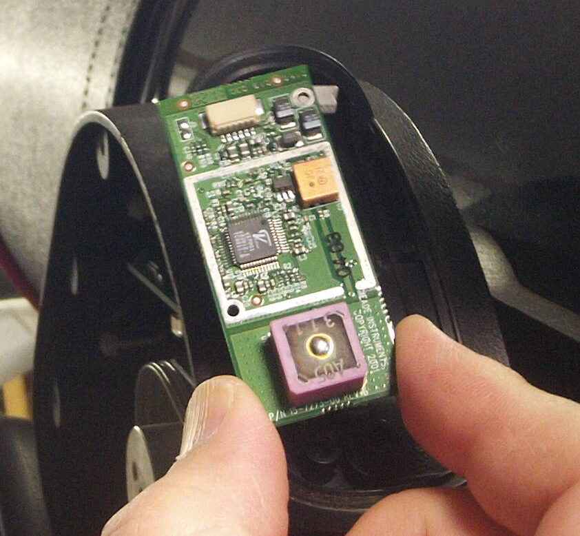
The 25 year old GPS module in my LX200GPS telescope has great difficulty getting a GPS fix. (My telescope is on a wedge, so the antenna is facing north instead of “up”, plus the backup battery died and is extremely difficult to replace without removing the telescope from the wedge. The biggest reason is that it is 25 years old.)
So I bought a modern BN-280 GPS module ($25) and a $10 USB->Serial TTL programmer, and replaced it. There are some technical details you need to get right to make it work (4800 baud, sending only $GPRMC messages, getting the wires hooked up right) but the overall process is relatively straightforward. Above is my howto video, and below is my big text dump:
Update: If I were to do this again, I’d buy this breakout board with the 6pin JST SH connector on it to make the soldering job much easier: https://www.pololu.com/product/4773
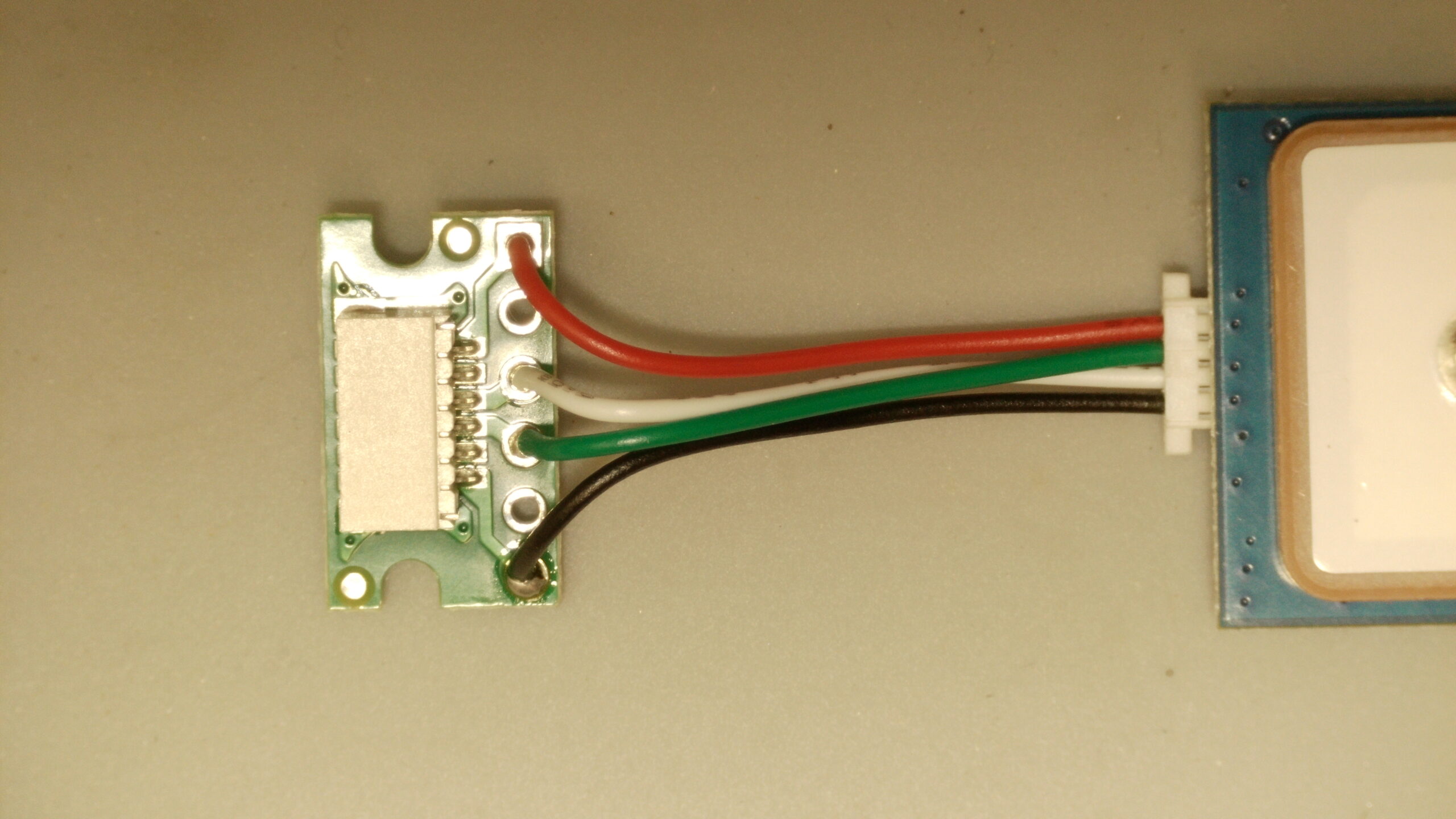
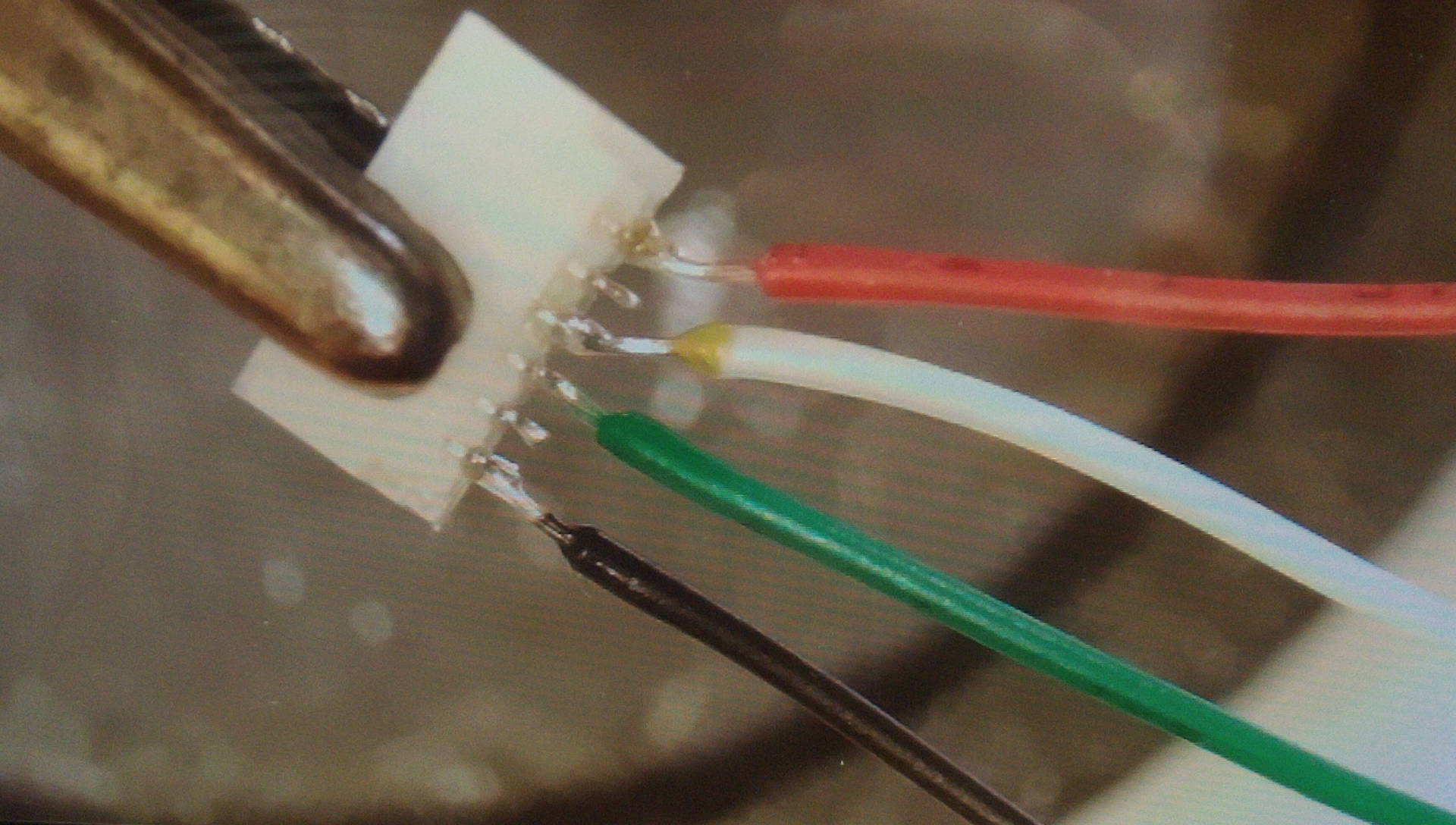
If you want to make a direct “plug in” replacement, you will need a JST SH 6 pin female receptacle (1.0mm pitch) to solder the wires from the GPS module to. [This plugs into the wire that comes up out of the left fork arm…see my video for how to open it up and get access…] I bought mine from Sparkfun for $0.95 each (+ lots of S/H). It’s part number “PRT-10210” JST SH Horizontal 6-pin Connector – SMD and is a real pain to solder onto. You can also buy them in a 20 pack from Amazon. (But unfortunately the male ends have the wires pre-attached, so you’ll need to solder to those tiny little SMD parts still……) Alternatively, you could just cut the wires coming out of the telescope and solder onto them, or use the male end that comes with wires and extend it out and make your own connector, as it plugs into the left fork circuit board.
The Beitian BN-220 GPS unit has a 4 pin header, and provides 3 sets of cables that plug into it (1 male pins for a breadboard, 1 female sockets to go over pins, and one double ended connector which you can cut off to solder to your own things)
Pinout from left to right is:
1 – Black Wire – Ground
2 – White Wire – GPS TX
3 – Green Wire – GPS RX
4 – Red Wire – + 3.3 volts to 5.0v power
The BN-220 unit is capable of 5 volt TLL signaling on the RX/TX lines, which I believe is important, because another unit that I tried which only does 3.3 volt signaling failed in my testing. [I can’t say for sure it was because the telescope RX line is pulled up to 5 volts (at very low current) but that is the only thing I can think of that would have caused the UART line to fail the way it did.]
Configure the GPS Module
I used the U-Blox u-center (25.06) software to connect to the GPS unit and modify the following settings to make it work with the LX200GPS telescope:
- The Meade LX200GPS REQUIRES the $GPRMC message. [It ignores any others.]NOTE: The newer BN-220 defaults to a “GN messages (Global Navigation) instead of GP (GPS) messages, which the LX200GPS won’t recognize, so to change this to GPxxx messages (USA GPS default, vs global GNSS default) you need to changes the “MainTalkerID” to GPS so it will produce the messages that the LX200 is expecting.Config->NEMA->MainTalkerID to 01-GP (GPS)
- You need to reduce extra messages that the LX200 is not looking for so that the telescope computer can process the GPRMC message without getting overwhelmed with extra data at 4800 baud. This reduces the amount of data that is sent so 4800 baud works fine at the default 1 Hz refresh rate.
I disabled all of the extra NEMA packets that the telescope doesn’t look for or need (GGA, GSA, GSV, VTG).
To do this, you go into Config-> MSG (Messages)
And then select each of the following and uncheck all the checkboxes (clicking send for each message)
F0-00 NMEA GxGGA
F0-01 NMEA GxGLL
F0-02 NMEA GxGSA
F0-03 NMEA GxGSV (This one reduces the most bytes….)
F0-05 NMEA GxVTGYou leave ONLY the F0-04 NMEA GxRMC message enabled.This allows the telescope to easy process the $GPRMC message as there is a lot of “down time” after it gets sent each second. Once you have disabled the extra messages, you can change the baud rate to 4800 (the rate expected by the LX200GPS telescope computer). - The baud rate is 9600 by default, so you need to change it to 4800 at
Configure -> PRT (ports) 4800
(After you do this, you’ll need to reset the port speed from 9600 down to 4800 in the u-center software to communicate with the GPS unit again…) - Of course, it is very important to save all of these configuration changes to FLASH so they persist across reboots,
Configure -> CFG (Configuration) Save Current Config(I selected the I2C and SPI flash options in addition to the default BBR/Flash/Eprom ones, as I’m not sure if the BN-220 module has built in flash, or if it uses a separate I2C or SPI flash chip, so I figured it was best to attempt to save everywhere, and it doesn’t hurt.)
After this, I confirmed that the BN-220 GPS unit works when powered by the telescope and the LX200GPS successfully gets a GPS fix from it. The minimum set of wires needed for the telescope to get a GPS fix is: +3.3v, GPS TX (to Telescope RX) and Ground wires.
[I did also connect the GPS RX to the Telescope TX line, just in case there is some reason to send commands to the GPS from a computer outside the telescope via the RS232 line, and it kept working…but I did not connect the battery backup or enable line.]
Looking down at the top of the connector, the pins to use are:
- Far Left: Ground [GPS black wire]
- Not Connected (Battery Backup I believe)
- Not Required (GPS RX/Telescope TX, measures 3.3 volts when telescope powered up) (GPS green wire)
- GPS TX / Telescope RX (Measures +5 volts when telescope is powered up!) [GPS white wire]
- Not Connected (Enable line I believe)
- Far Right – +3.3 volts power [ GPS red wire]
(I’d recommend looking at the photo above of the JST SH breakout connector from Pololu as it is much cleaner than the ugly wires soldered directly to the back of the JST-SH surface mount component shown above…)
 eFlash fuses on an u-Blox M8Q GPS to default 4800 baud and GPS only mode")

")
Thanks again for the fantastic tutorial.
Would you anticipate any difficulty or impossibility if I extended the wires from the receiver three or 4 feet and mounted that receiver externally while I was using the scope. Thanks again.
On my LX200 the GPS unit itself is mounted above the aluminum fork arm inside the plastic bump (but it is directly above the metal).
So as long as the GPS receiver itself is outside the metal shell you shouldn’t have to move it very far away. If you wanted to extend the wires 4 feet I expect that wouldn’t be an issue, as the power and RS232 shouldn’t have a problem with that extra length. The biggest potential issue would be wire management and making sure that that external wires don’t get caught in anything as the telescope moves around.
[For aiming, the telescope only needs the time and an approximate lat/long, so having the GPS up to 100 feet away from the telescope won’t change the math, but not sure the power/data would travel that far without a signal booster.]
I greatly appreciate your help thank you
You are welcome!