In a previous post I have shown how to physically mount six Nissan Leaf battery modules in two series groups of 3 parallel modules to build a 180 Ah by 16 volt Lithium (LiNMC) battery.
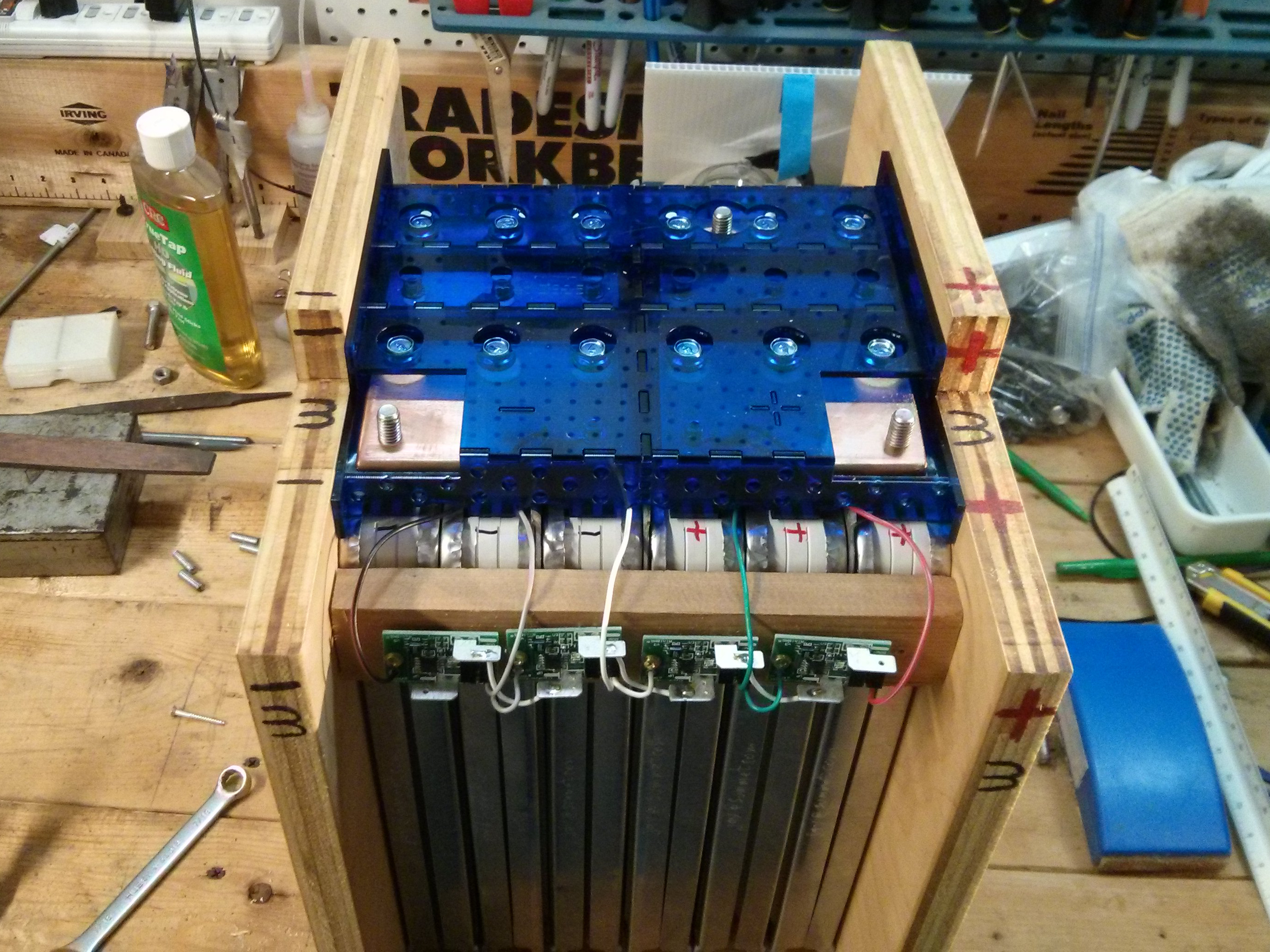
The batteries are covered by these very cool laser cut acrylic protective covers (which obscure the BMS wiring).
Anthony Felix asked for more information about the BMS units I’m using on my batteries, so here it is! (Jump down to the last picture if you just want to see where the BMS units are attached….all of the text between here and there is an explanation of WHY they are attached there…)
I purchased mini-BMS units from Clean Power Auto to use on my batteries.
The Mini-BMS boards serve two functions:
First, they monitor the cell and “sound the alarm” if the voltage goes too high (overcharging) or too low (overly discharged).
Second, when the battery pack is charging, or any time a cell voltage is “too high” they attempt to actively “balance” or manage the cells to make sure that they all reach the “fully charged” level without any cells going to the “overcharged” level. If the voltage reaches the “100% charged” level (4.1 volts in the case of LiNMC chemistries such as in the Nissan Leaf) the mini-BMS board will shunt a resistor across the cell, “burning off” about 0.5 amps of power in an attempt to bring the voltage down to just below 4.1 volts, or at least keep it from raising any higher.
How they “sound the alarm”
The mini-BMS cells are designed to be linked to each other and form a large “loop”. When all is well, they conduct through the entire loop from one end to the other. If any mini-BMS board detects a problem (overly high voltage, or overly low voltage) they will disconnect (or “open”) the loop, meaning that the other end will drop to zero volts, indicating that a problem exists.
When does the loop open?
If the voltage raises to the maximum allowed (by the battery manufacturers specifications) of 4.2 volts, the mini-BMS board will “open the loop”. Also, if you are discharging the cell too much (such as driving your car longer than you should) and the voltage drops too low, the mini-BMS will also “open the loop”.
Who “listens for” the alarm?
You need a head unit, or intelligent charger, or EV charge controller that connects to a loop based BMS system. It will apply 5 volts to one end of the loop, and check to see if most of it (4.8 volts or so) comes out the other end. If you are currently charging the pack, it means that the charger needs to shut off, to protect the cell that reached 4.2 volts from getting overcharged. If you are currently drawing from the pack (e.g. driving) it should sound an alarm or put the vehicle into turtle mode to reduce the draw and tell the driver that they need to pull over and charge the pack!
I’m using an EVCC unit from ThunderStruck motors to control my chargers and sound the alarm when driving, and it is functioning as my head unit for the BMS loop, but you can also buy a head unit from Clean Power Auto to go with their distributed mini-BMS boards.
When I purchased the BMS units, I didn’t know exactly how I was going to arrange the modules into my batteries, so I bought individual cell BMS units, designed to be mounted across each cell. If I were to do this project again, I would definately purchase one of the “4S cell board” ($55) for the entire 16 volt battery, as opposed to using four individual “cell modules” ($12.75 each, or $51). The extra $4 is well worth having them all connected together when you purchase them, as I spent about 30 minutes per battery soldering together the 4 BMS units.
But, since I already had the individual cell units, I soldered together four individual units myself to make the equivalent of a 4S cell board for each 16 volt battery, and mounted them onto a piece of wood.
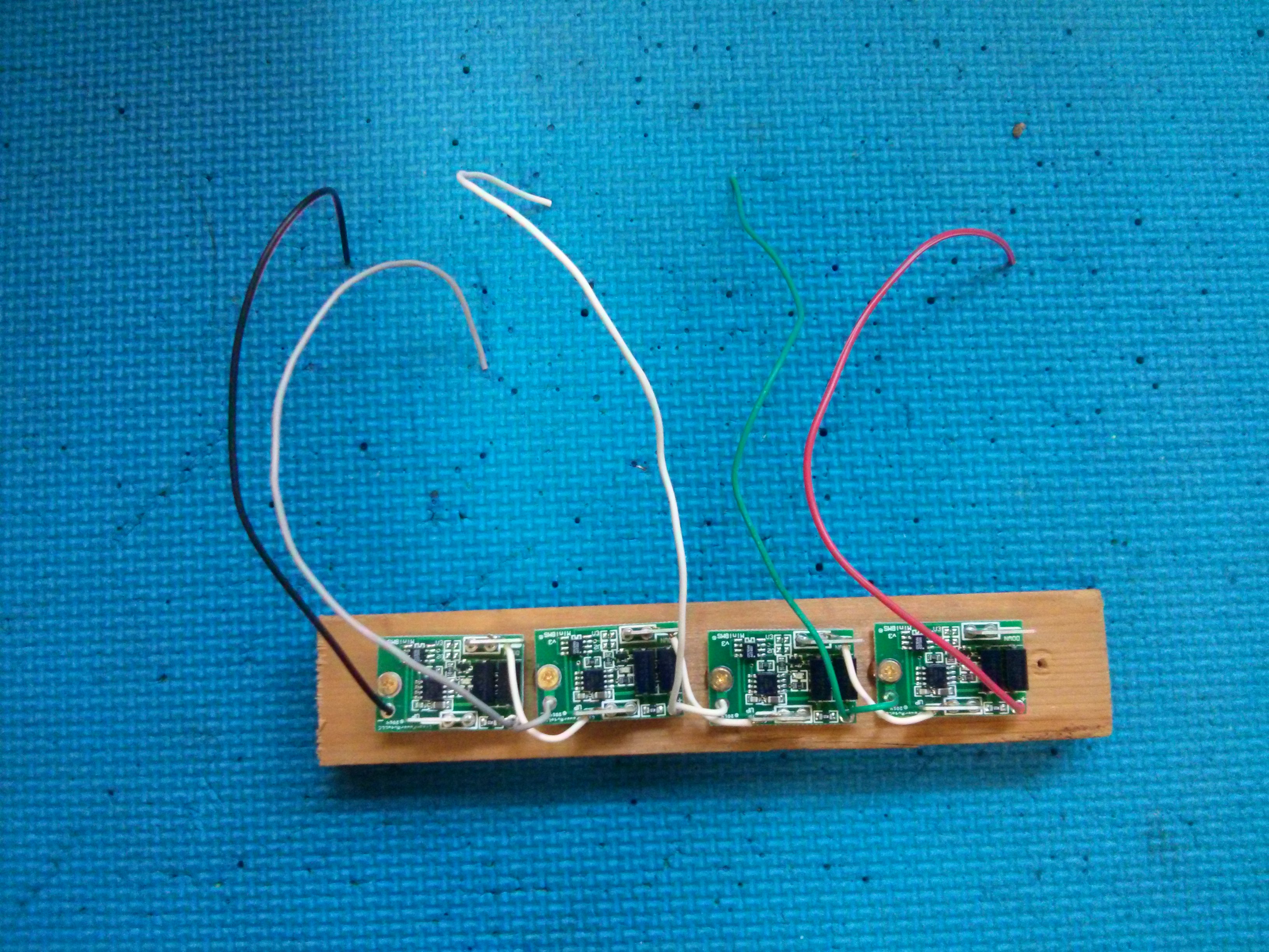
This assembly is attached to the 16 volt battery by five wires. (It also will have two wires that form the left and right side of the “loop”.)
Leaf Modules have two cells!
To understand the attachment points, you need to understand how a Nissan Leaf module is constructed internally. It actually has four cells inside it, 2 series sets of 2 parallel cells, each cell rated at 30 Ah. When you connect cells in parallel, their voltage will always be the same, so you can essentially treat them as a single larger cell. This means that for all practical purposes, the Nissan Leaf modules is a series arrangement of two 60 Ah cells. Each cell is nominally 4 volts when charged, so a leaf module (with its 2 series arrangement) is around 8 volts. (8.4 volts absolute maximum.) BUT, if you measure from the negative terminal to the “sense” terminal in the middle, you get 4 volts, or one cell. If you then measure from the “sense” terminal in the middle to the positive terminal, you get another 4 volts from the other cell.
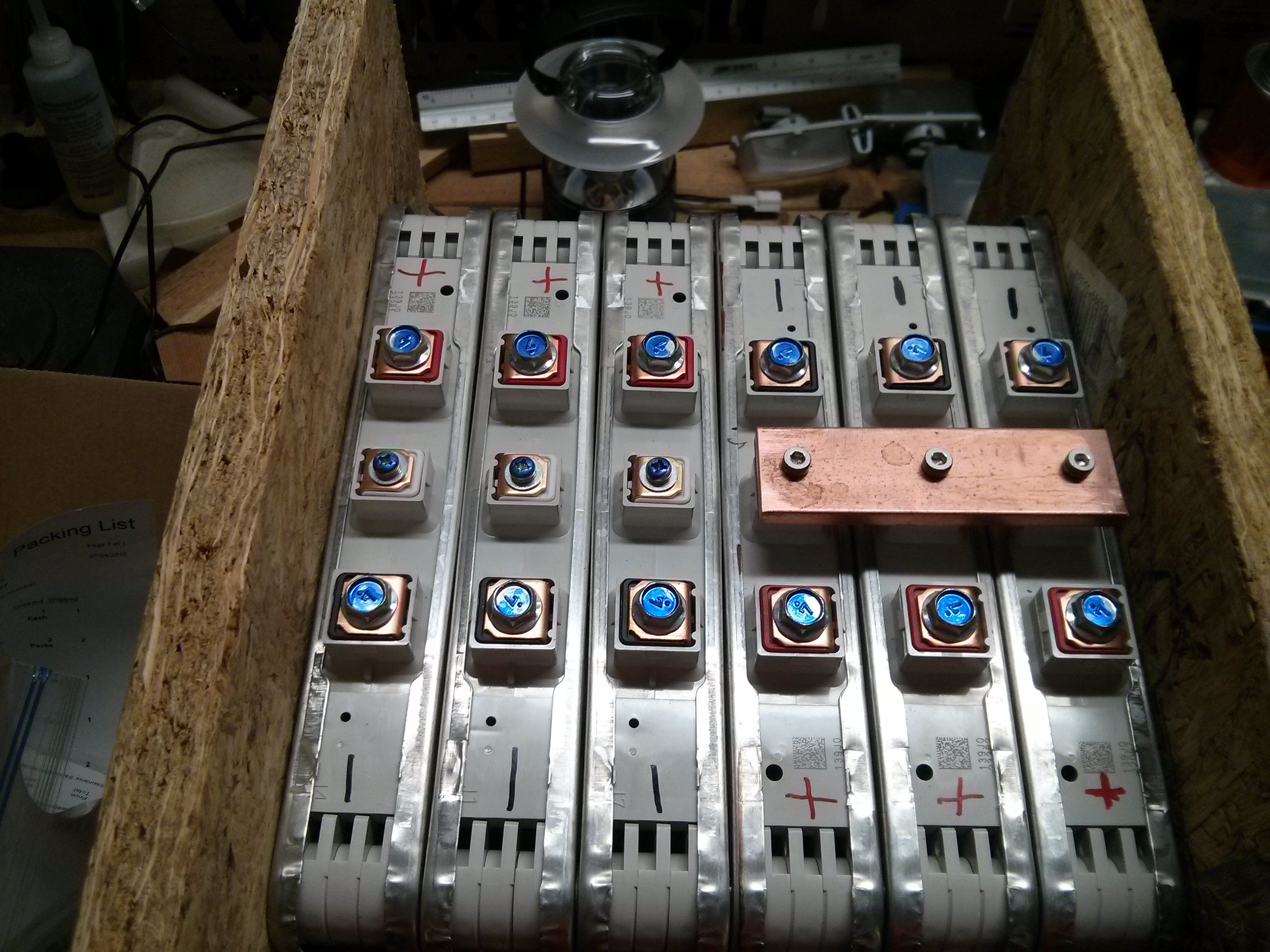
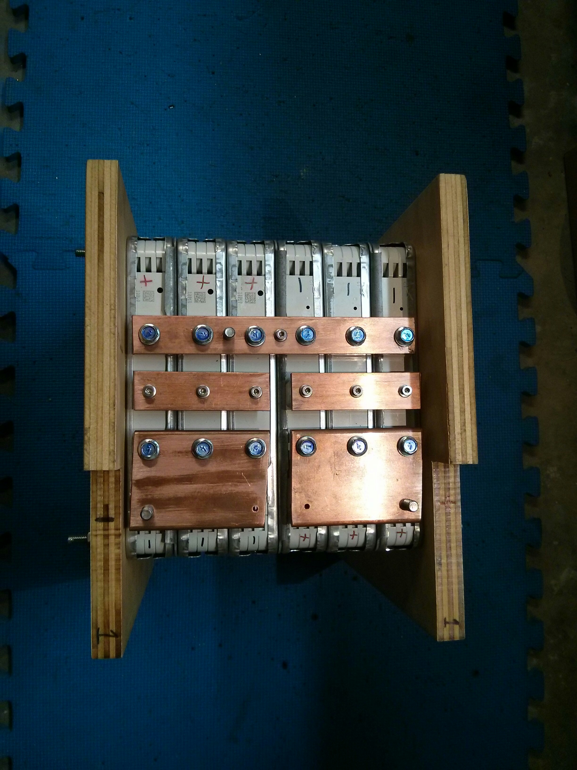
This is why I am connecting the sense terminals together for my parallel set of 3 Nissan Leaf modules…to REALLY keep all six of the cell in the lower half (and all six of the cells in the upper half) of the 3 leaf modules in parallel. The photo below shows one of my “sense terminal” buss-bars. Hopefully, no real current will flow through this buss-bar, it’s just there to keep the parallel cells at the exact same voltage. I could have used much smaller copper stock for this connection, but I found it was easier to use the same copper for all of the connections.
Because the mini-BMS boards are cell level boards, you need TWO (2) BMS boards for a single Nissan Leaf module. My 16 volt battery has six leaf modules, BUT, I have two sets of 3 in parallel. This basically means that I have a total of 4 cells in series (except my 4 cells are 180 Ah each, because they are made up of 3 Nissan leaf modules, at 60 Ah, each of which is actually two 30Ah cells inside the module (just to further confuse you).
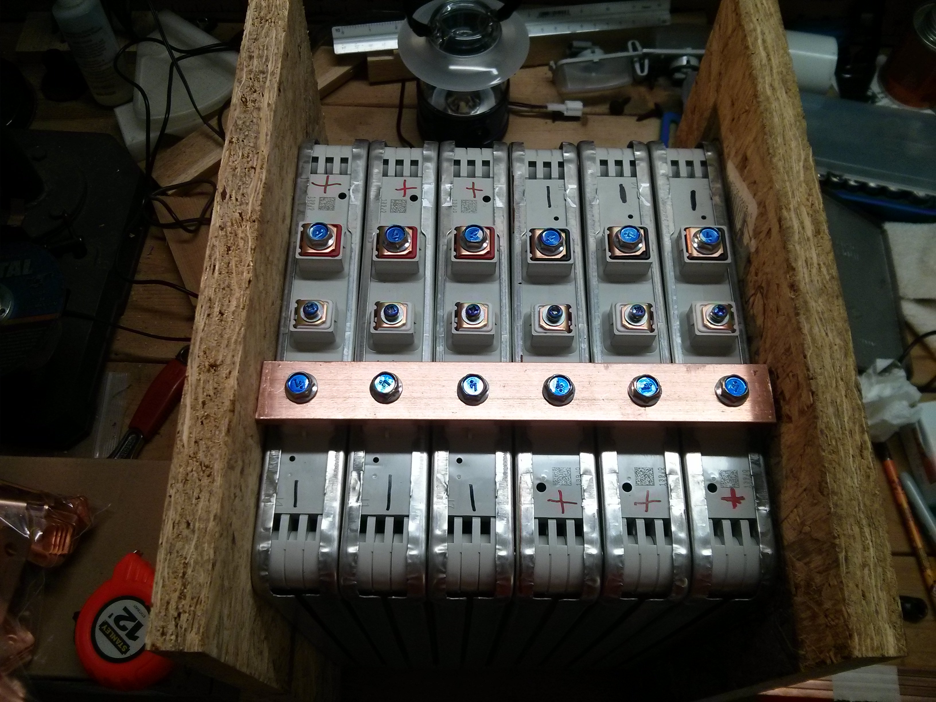
The picture below shows my “series” buss-bar, which connects the three positive battery terminals (on the right) to the three negative battery terminals (on the left), putting the two parallel groups of 3 modules “in series”.
Below you can see that I have rotated the battery and installed the two (Positive and Negative) “terminal” buss-bars. By connecting to the two terminal buss-bars, you get a 16 volt potential for my entire “battery” of 6 Nissan Leaf modules.
Back to the BMS connections
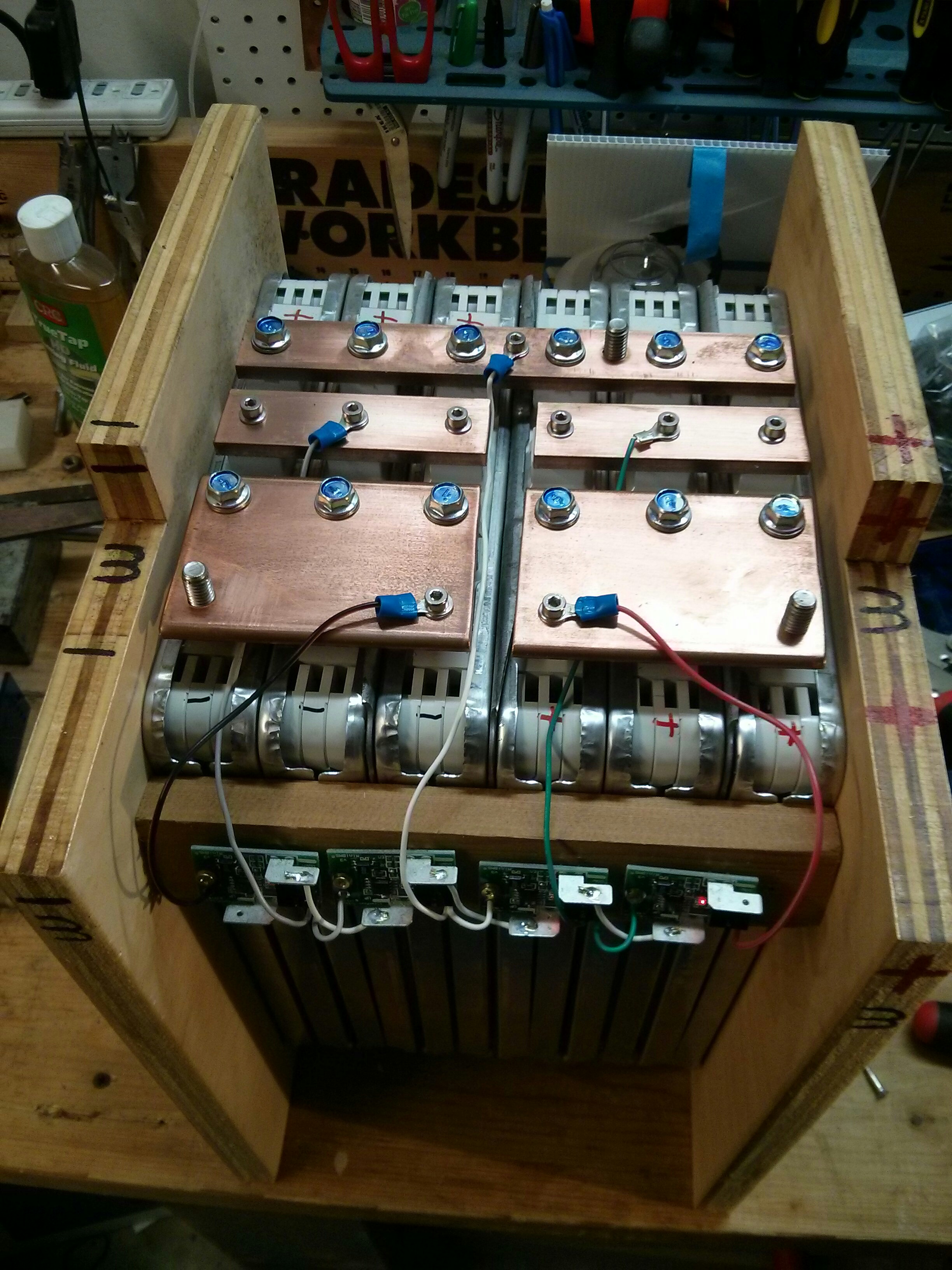
In my 16 volt battery, I have six Nissan Leaf modules total, arranged in two (in series) “groups” of three (in parallel) modules . The lower one which is the most negative side, and the “upper” one which is the most positive side of the 16 volt battery.
Individually, the four BMS units each have two wires (+ and -) and need to be attached in the following places so that they span each of the 4 cells:
1. To the most negative terminal, and the sense terminal of the lower group.
2. To the sense terminal, and the positive terminal of the lower group.
3. To the most negative terminal in the upper group, and the sense terminal of the upper group.
4. To the sense terminal of the upper group and the most positive terminal of the upper group.
Note that BMS unit 2 can share it’s negative connection with the positive connection on BMS unit 1…. and BMS unit 3 can share it’s negative connection with the positive connection of unit 2, and unit 3 can ALSO share it’s positive connection with the negative connection of unit 4, etc…
So in this way, it is possible to have five wires connect all four BMS units. (the end most wires are individuall, but the 3 middle wires are shared by the BMS unit “above and below” that connect.)
The picture below will probably serve to explain things a lot better than all of the previous words. Click the picture to make it bigger. Note that the small white wires connecting the BMS boards are part of the larger “loop”, but that they currently do not have the connections to the batteries to the left or right of this one.


Pingback: Thunderstruck Motors dual TMS2500 & EVCC charger package | Jay's Technical Talk
Pingback: Nissan Leaf Modules powering my S-10 Pickup conversion | Jay's Technical Talk
I read with interest your Leaf Battery post. I have just purchased a salvaged Leaf. My interest is in solar/off grid use. Appreciate your comments re: BMS…I was wondering how the BMS would work with 8v lithium battery…but now I see the sensing terminal cuts the battery module down to two 4 volt chunks.
Curious as to how you sold off the rest of the car? and how you decided on prices for items sold. I certainly would like to recapture some of my investment. By my calculations commercial lithium batteries ie Calb/Winston run about $260-280 or more per kWh. I spent $4.8k on this car so my price per kWh is about $200. Your final price was a bargin!
Regards…Richard in Oregon.
I spent around 4.1K for the car, but made almost all of that back selling parts. A lot of the pieces I sold on ebay, and I sold larger pieces locally on Craigslist. (As I’m in the Atlanta area, which is the 2nd largest market for Leaf’s after CA, there are enough of them on the road around here that I could sell parts to people.) I would typically look up the “new” price on auto sales websites, and then ask about 25-40% of the new price for the “used” parts. After selling various parts to auto-body shops I found a guy who decided to buy the rest of the car to use for parts (he had purchased 2-3 wrecked leafs and was fixing them up). The process of selling all the parts took up a lot of time and effort. I’m currently at $40 per kWh on the cells.
I have 2 leaf and I am using one to take the battery rearrange the modules and placed in the trunk of my other leaf.
I perfectly understand how you built the modules and how to connect the mini-BMS, but here is my question:
Once all battery packs(8) are connected in series, How you charge the battery? Or what kind of charger do you use?
Or what is the charger max voltage? (must have a cut-off voltage regardless if the mini-BMS will discharge anything above 4.1V)
You can read about my charging system here:
https://www.summet.com/blog/2016/01/03/thunderstruck-motors-dual-tms2500-evcc-charger-package/
The charger will be shut down by my mini-BMS loop if any cell reaches 4.2 volts.
For maximum charging voltages, I have a few different profiles that I can pick from. I use 130 volts (4.0625 volts per cell) for daily usage, which is around 80-85% charged, and use 131.4 (4.106 per cell) for “100% charged”. I will occasionally go up to 134 volts (4.1875 volts per cell) for top balancing. (The Mini BMS units start to shut any cells that reach 4.1 volts, and 4.2 volts is the absolute max).
If you are going to be trying to use the second leaf pack to add range, you will need to keep all 48 modules in series, or a 393 volt pack. One option that you could try is to wire each module up in parallel with an existing module inside the original leaf battery, and let the leaf’s onboard charger and BMS system do all of the charging and discharging. (Basically, from the Leaf’s point of view, each module is suddenly 120 Ah instead of 60 Ah.)
Of course, this takes a lot wires (97), and somebody has already tried it and burnt their leaf up. (due to water intrusion into the original factory battery, not necessarily because the method was flawed…)
https://www.youtube.com/watch?v=2cIo95W-vfE
I see that the clean power auto company doesn’t sell these BMS modules any more – any suggestions for a replacement?
If I were to buy a BMS today I’d probably go with either the Elithion or Orion systems.
http://elithion.com/
https://www.orionbms.com/
They are both a bit more advanced than the MiniBMS system.
Have you looked at Batrium.com. I am going that route. They have a module specifically made for a Leaf.
The mini-bms system that I am using now is no longer sold. I would appreciate the ability to monitor per-cell voltages using one BMS system. (Currently I’ve re-used my old “PakTrakr” system which gives me a voltage reading for every two cells. If one group of two cells shows a voltage drop I can pull out a multi-meter to figure out if it’s both of them or just one of the two. (The PakTrakr doesn’t do any balancing or shunting, it’s just a battery voltage monitor originally desinged for lead acid batteries…so as far as it’s concerned I have 16 8 volt golf cart batteries (as opposed to 32 LiIon cells in series.)
The Mini-BMS does top balancing (current shunting) and sounds an alarm if any cell voltage gets too low (or shuts off the charger if any cell voltage gets too high) so it is handling the top and bottom end of things well enough, and combined with the PakTrakr I have enough pack monitoring for my current needs, but if I were to do it over again I’d probably spend extra for a BMS that had a per-cell reporting feature like Batrium.
We would love to talk to u about the leaf BMS .. I am assuming you , also could not make it work??
Any thoughts would be helpful… the Mini is out of business… we have beta tested $$$$$$ many and found one that is just OK. It’s on our web page …www.Greenshedconversions.com
I never tried getting the Leaf BMS to work as I needed a different pack voltage. Check out WolfTronix’s Leaf Pack Sniffer on YouTube, he has success communicating with the Leaf BMS if you are going to keep the modules in the same configuration:
https://www.youtube.com/watch?v=IB4Q1A2XOXA&list=PLQdu_G7xyFIR29L5izNZavf4Uf8IMWuZm
If I have to replace the MiniBMS I would probably go with the Batrium system.
You can find my contact information here: https://www.summet.com/contact.html
Great video!
Hi , i appreciate all i saw you done here , it is quite educational and enjoyable , my request is since im new to using lithium ion packs can you assist me with a diagram to connect a 4s bms to the nissan leaf packs i have 4 cells arraged as yours are for 16v but im having difficulty connecting the bms , should i have gone with 6 cells as you have , getting the leaf packs are not an issue as i have a nissan leaf dealer close by where i purchased mine . I’m hoping to use mine for off grid solar. , thanks in advance
Each Leaf module needs a 2S BMS, because they are arranged 2S internally. (One between negative and the middle sense terminal, and one between the middle sense terminal and the positive terminal). You just repeat those connections for each module you have in series. (You can “combine” the “top” of one BMS and the “bottom” of the next one, as they connect to the same point on your series arrangement of modules.)
If you have a 4S BMS module, it typically has 5 wires. One for the most negative, one for the most positive, and three for the connections between the 4 cells.
Great post. Seeking your assistance. I have 48 leaf modules arranged in 4s12p configuration. I am working with this for a 24v system. My inverter can manage up to 33v. My problem is with the bms. I am thinking of a 24v 8s bms but I am not sure the amperage of the bms I should buy. Any suggestion?
Any hobby or e-bike BMS you buy won’t be able to handle the full current of your battery pack, but could at least let you know if any individual cells go out of balance. Each leaf module can easily supply 30-60 amps (they are fused at 200) so 12p would be 360-720 amps.
You probably want to buy a “real” bms that interfaces with your charger to turn it off in the case of a high voltage event, and controls a contractor to disconnect your inverter/load in the case of a low voltage event. I haven’t used it, but a lot of people recommend Orion: https://www.orionbms.com/
Older boats have 32 volt systems. So hard to find anything. This looks interesting as we all know 16×2=32
Yes, Leaf modules are great for any multiples of 8 volts (24, 32, 48) but not so great for 12v systems as you have to use “half” of a module at the end, plus draw current via the ‘sense’ connections which are not rated for as much current….
I have leaf mods 3series 3 parallel for 24 volt. Can I cheaply add a bms to this?
Probably. There are a lot of 6-S BMS modules designed for Ebike applications that may be able to handle the 4.2v max leaf cells. (Note that a leaf module is 2-S internally, so your 24v battery is actually 6-S from the BMS perspective). The key is to find one which allows you to change the min/max per-cell voltages, or already has a profile that is compatible with the Leaf chemistry and voltage limits (LiMnO2 or NMC??) (4.2v per cell max). It also depends upon how many amps you want to draw, as a lot of the smaller e-bike BMS units are limited to 40-60-80-100 amps.
Of course, you can use the BMS to monitor, balance, and protect the battery in charging situations, but have a secondary tap off of the battery (unprotected by the BMS) for large current draws. I have not researched/tested any specific BMS’s for this application (yet) so I don’t have any specific recommendations.