How to convert a Denford / ScanTek 2000 Micromill to LinuxCNC / Mach3 control
Part 1 – 3 Axis control
Video here, details below
My ScanTek 2000 ScanMill (A re-branded Denford Micromill 2000) has a dispatch date of 2005, which means that it’s main controller is a Baldor NextMoveST card. This card supports USB as well as RS232 control signals, and runs a custom (MINT) programming language that can offload machine control from the host computer.
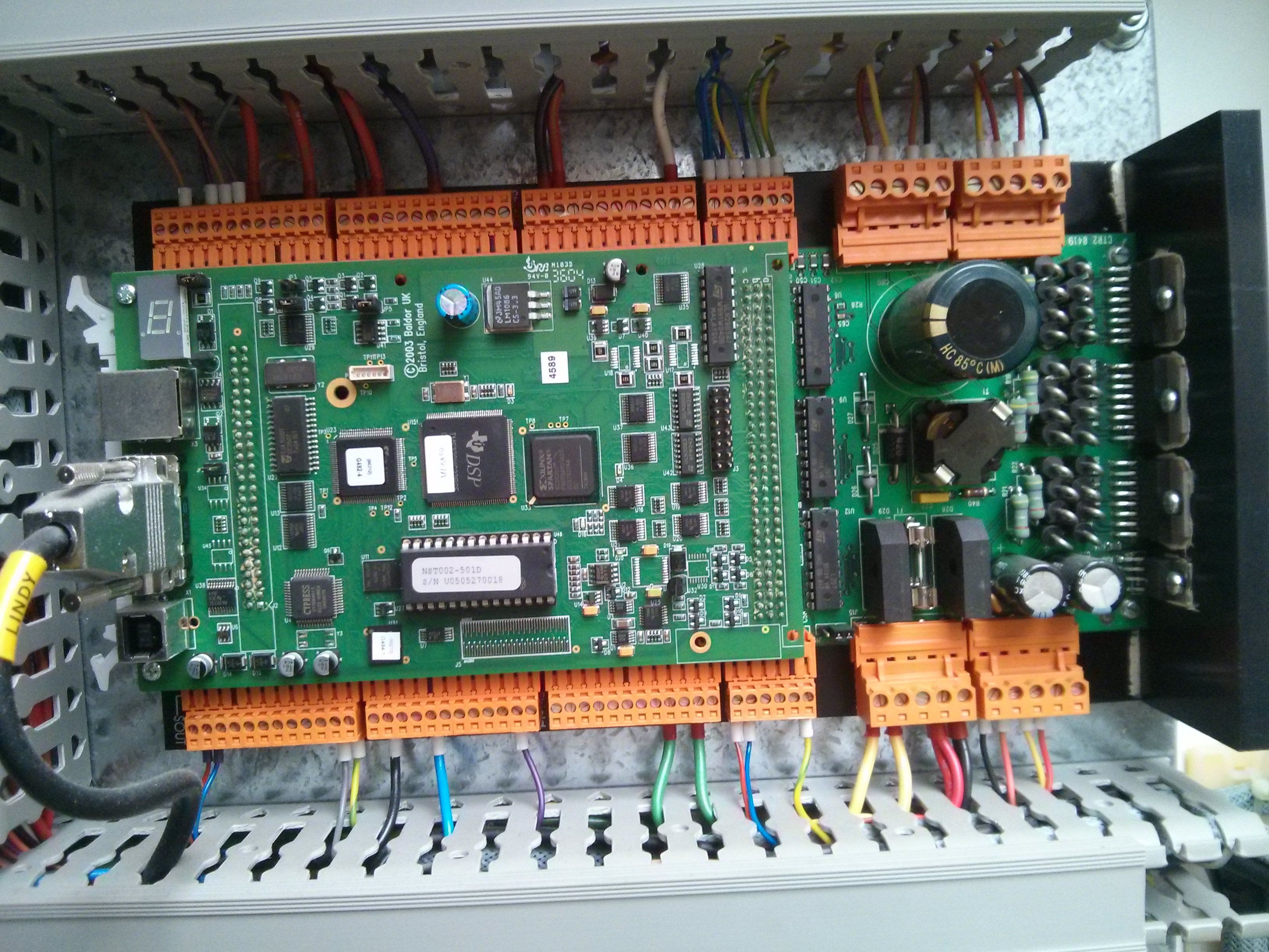
You can actually download the MintNC development tool from the Baldor website that allows you to upload custom Mint programs to the card, and could make it (for example) do some simple operations offline with no driving computer. However, I am not interested in writing Mint code to interpret g-code, so I’m going to set it up so that LinuxCNC (or Mach3) can control it via a parallel printer port.
To do this, I will remove the top card from the NextMoveST entirely, and leave just the bottom card. The bottom card is where the stepper motor drivers live, and I can plug directly into their step and direction pins, plus grab +5v to drive my break out board.

First, connect to one axis (I used X) and get your parallel port Break Out Board (BOB) and software working. Mach3 offers a free trial and is easy to set up if you are running Windows, or you can use LinuxCNC. [I used Mach3 for set up, and plan on switching to LinuxCNC for actual operation.] I purchased a cheap laptop that was old enough to have a parallel port built in to have a small dedicated machine for the mill (The Thinkpad T and X lines in the 30, 31,40,41 range are good options.)
The 96 pins are arranged in 32 rows of 3 pins. The columns are ordered “backwards”: C,B,A with C on the left and A on the right.
C1 B1 A1 <--- top right

C2 B2 A2

....

....

C32 B32 A32 <--- bottom right
I used a 96 way DIN connector from DigiKey (PN:1195-1197-ND $4), but you could use three 32 pin female sockets to connect to them. The [wire color] indications are just the colors of the wires I used, so you can match them up with my photos, the actual color doesn’t matter as long as they conduct electricity, but red for +5 volts and black for ground is a good standard to follow. I used stranded AWG 22 hook-up wire. I decided on yellow and white for step and direction because I don’t use those colors as much, and wanted to make sure I used those rolls up.

My BOB needed a 5v supply, so I got it from the board,
A1 - VCC    [Red wire]

A3 - GND    [Black wire]
NOTE: On the Dispatch date 2005 ScanTek 2000 I had, they were using a
Baldor (now ABB) NextMove ST. The card looks like it is mounted “upside down”
as all of the text on it is upside down, BUT, the top of the card as mounted in
the Denford / ScanTek steel case still corresponds to pins c1, b1, a1. Testing for 5V between A1 and A3 verifies this.
I used the baldor-eurocard-schematic-and-pinout.pdf document found on the Denford forum to verify the pin assignments below.
To get your BOB / Parallel cable / Software working, you only need one
stepper connected for testing (I used X).
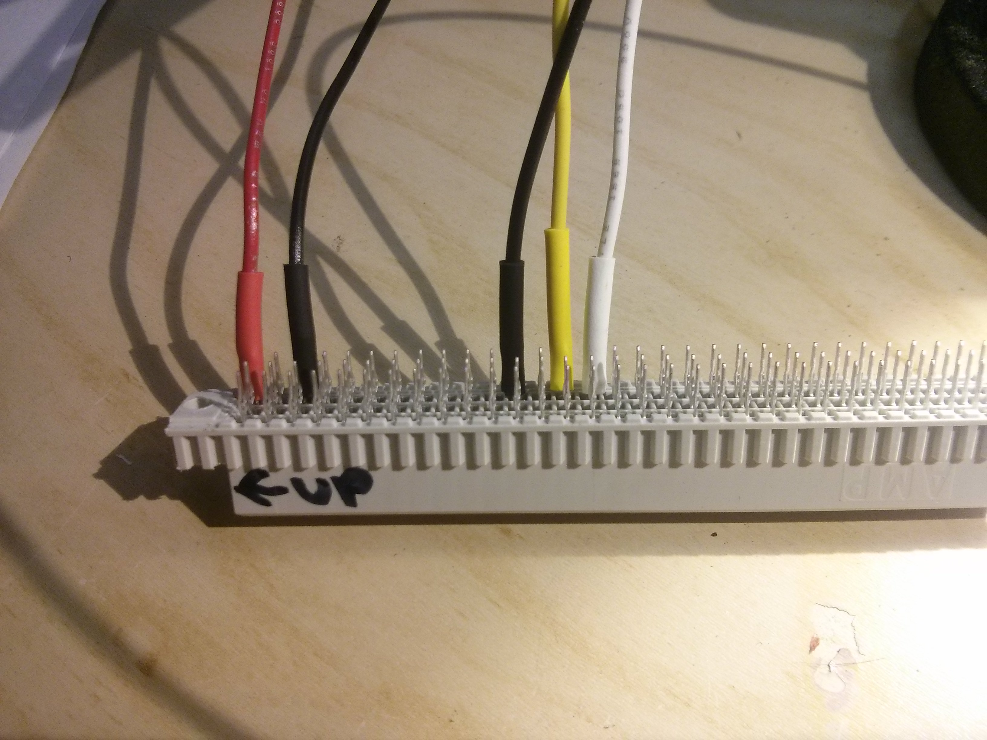
12A - X Gnd GND/Common on parallel port card. [black wire]

14A - X Step Pin 3 (sherline standard) [yellow wire]

15A - X Dir Pin 2 (sherline standard) [white wire]
The non-Sherline layout is: (step & direction reversed…)
2=X step, 3=X dir, 4=Y step, 5=Y dir, 6=Z step, 7=Z dir, 10=Limit, 11=Z home, 12=X home, 13=Y home, 18-25= Ground, All others are not connected
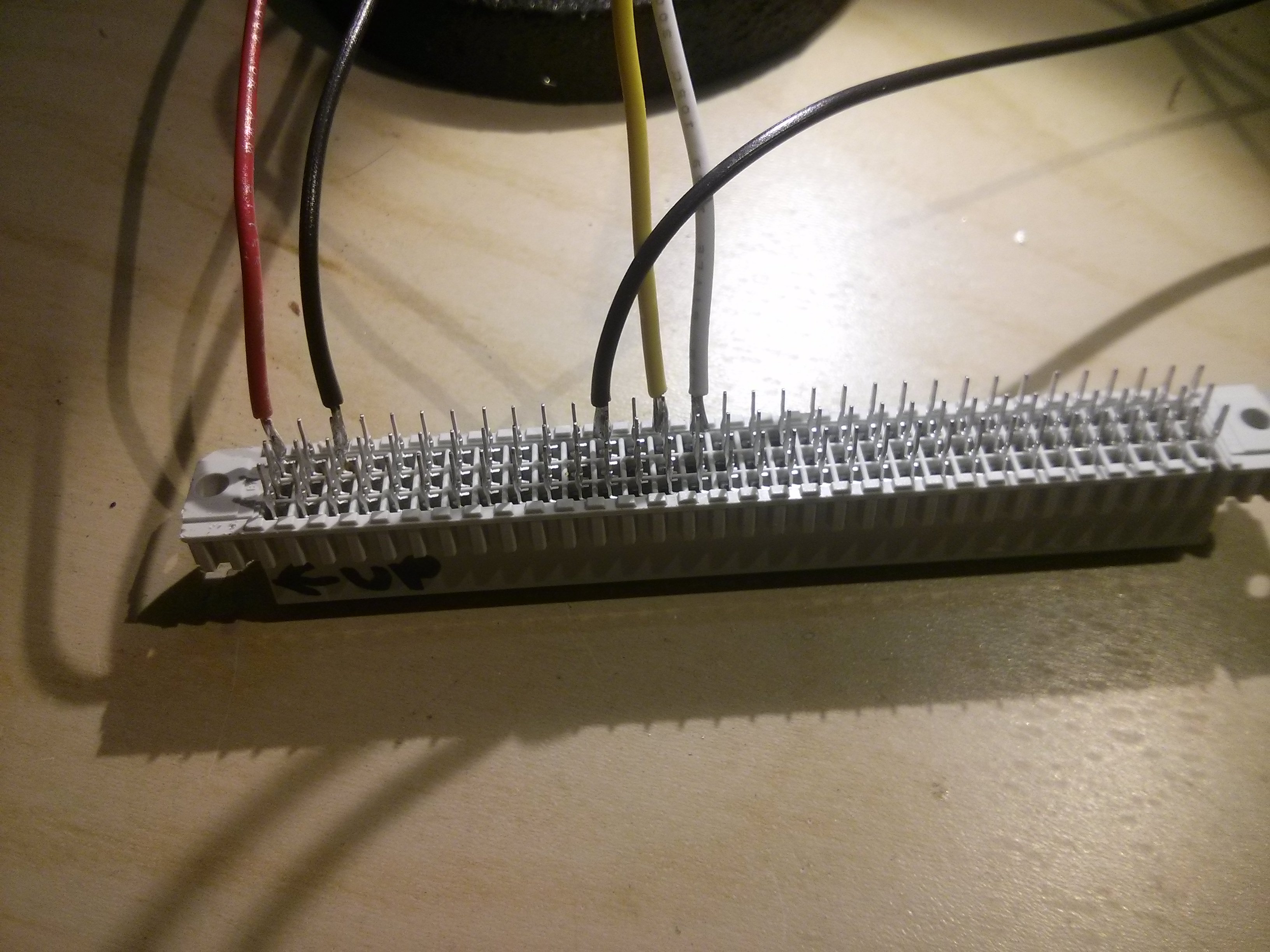
I used pieces of 1/8″ (or smaller if you have it) heat shrink to cover each solder joint, but if you don’t strip extensive lengths of wire the DIN connector pins will keep them from moving, so this is not really necessary unless you expect a bug or falling object to short out some connectors.
Then get your software to work and jog the X axis. Note that on Mach3,
the first parallel port is port 1, but the configuration dialog defaults to “port 0” for everything, so change the port to 1, and the pins to 2 or 3 for step/direction. You will also have to disable the ESTOP input or set it to active low so that it won’t complain about ESTOP being always on until you connect up the ESTOP button.
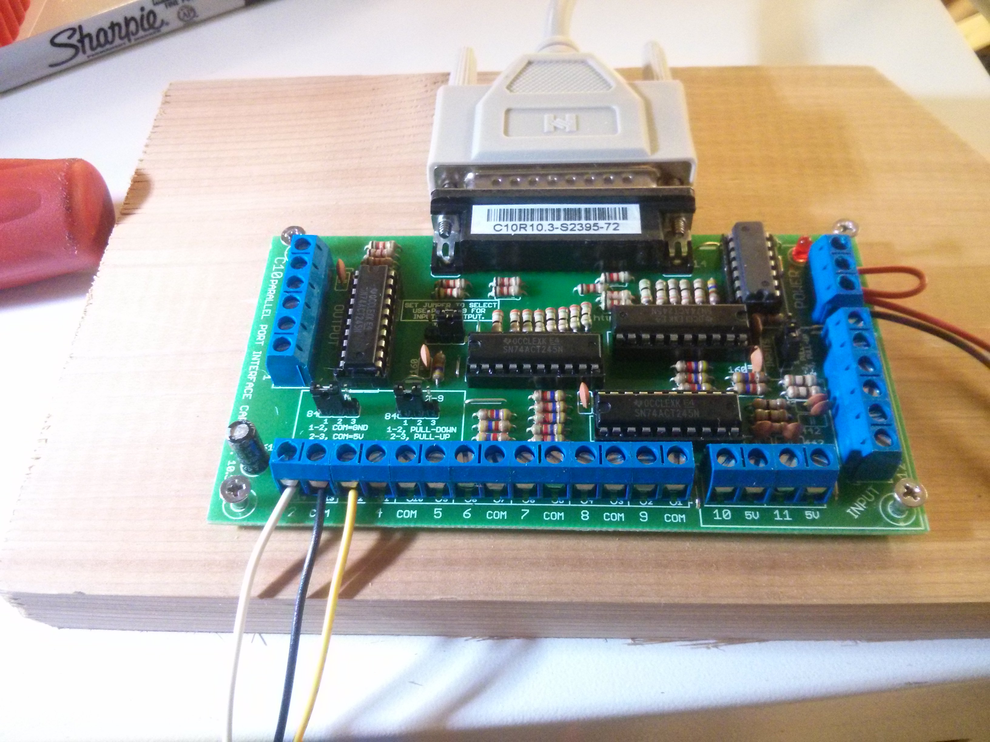
The breakout board I bought was from CNC4pc (the C10 – BI-DIRECTIONAL PARALLEL PORT INTERFACE CARD) for $30. I was annoyed to find out that it used a DB25 female connector (the same as my computer) so that a 25 pin Male2Female standard parallel printer cable would not work without a gender changer. A DB25 male/male serial cable however allowed me to plug it directly into my parallel port without any extra adapters. It may turn out later that I will need a 0-10v DC isolated spindle control signal, which this break out board does not offer, but I’m hopeful that I’ll be able to find a pin on the 96 way header that controls the spindle speed using TLL logic levels.
Don’t forget to get +5 volts to the Enable connection as well. You could use this on an EStop for a physical shutdown of the breakout board.
[Technically, you could connect the wires from a parallel port cable directly to the 96 way connector without an opto-isolating break out board, but if something went wrong it could fry your parallel port or motherboard, so the break out board is inexpensive insurance, and the screw terminals make attaching wires nice and easy.
After you get the first axis working, spend the time to solder up the rest of them as follows:
14B - Y Step Pin 5 (serline standard) [yellow wire]

15B - Y Dir Pin 4 (sherline standard) [white wire]

17B - Y Gnd GND/Common between 4/5 on BOB [black wire]
14C - Z Step Pin 7 (sherline standard) [yellow wire]

15C - Z Dir Pin 6 (sherline standard) [white wire]

17C - Z Gnd GND/Common between 6/7 on BOB [black wire]
(I’d suggest you do the Y axis first, so that you are not fighting to get
behind the Z axis wires when soldering them.)
Watch the video above to see my steppers actually move.
Check out part 2, where I hook up the homing switches on each axis, as well as the E-STOP button.
The biggest remaining job is to figure out how to enable the spindle control board. My reading online indicates that it takes a DC 0-10 volt signal and maps that to the spindle speed. The difficulty is that this voltage is with respect to the AC voltage on the spindle controller board, so it’s really from 110-120volts or soabouts, which means you can’t just plug it into a 5 volt break out board and expect anything good to happen. You need a completely isolated 10 volt supply for it. However, the NextMoveST board does drive this spindle driver board, so I am confident that I can drive one of these 96 pins with a PWM signal to get the spindle running. Of course, now I just have to find the correct pin.
Check out Part 3 where I get the spindle to turn on and off (at full speed only) using a pin on the breakout board. In Part 4 I get PWM speed control working.
My overall goal is to be able to connect to the mill using ONLY the 96 pin connector, to keep the upgrade as neat and clean as possible.
 interior photos")


Cool write up!
I don’t know much about electronics but I picked up a denford micromill for a deal that was too good to pass up. everything is intact and I also have a gecko g540 controller, power supply and a uc100 parallel port usb controller with a bunch of accessories, wires, limit switches. estops etc. etc.
I use solidworks, and camworks and would like to run the machine with mach3. What do you suggest I do with what I have so far to get the machine running? Do you have any advice for wiring and tech details?
Thanks,
Doug
If you are using the Gecko g540, you would remove the denford control board entirely and just wire each of the 3 stepper motors directly to your Gecko G540 board, as it includes stepper drivers. (You’d use the UC100 to plug the gecko into your computer via USB.)
The technique I present on this website assumes that you will be making use of the pre-existing stepper drivers that exist on the bottom card of the existing Dalfor NextMoveST controller board.
Hello, may be you can help me. I bought a MicroMill 2000 with no software and I have no idea how to program this machine with out expend to much money in software.
Thank yoy
The only software that works with the stock MicroMill is relatively expensive ($750USD was the quote I received), and is only available from Denford.
http://website.denford.ltd.uk/products/vr-cnc-milling-5/
If you follow the directions here and elsewhere, you can replace the stock control board with a parallel port breakout board (BOB) and control it with other 3rd party software such as the inexpensive Mach3 or free LinuxCNC.
Pingback: How to convert a Denford / ScanTek 2000 Micromill to LinuxCNC / Mach3 control: Part 2 — Home switches & E-Stop | Jay's Technical Talk
Pingback: How to convert a Denford / ScanTek 2000 Micromill to LinuxCNC / Mach3 control: Part 3 — Spindle Motor Control | Jay's Technical Talk
Is there any way to find out or could you tell me the pins i would need to connect from my C10 B.O.B. to my Smartstep/3 controller board. I cant find the information anywhere. I do have a multimeter but can figure how to find out what pins i need to connect to.
Thanks!
I’m afraid I don’t have a Smartstep/3 control board on mine so I don’t know the pinouts for it. But if it is a MINT control board from Baldor it is likely that if it has a 96 pin connector you will have the exact same pinouts. I would test by doing a continuity test from ground to a pin that is supposed to be on a limit switch. If it is connected when the limit switch is pushed, it’s the right pin….you can check to see if my Pinouts will also work for your board.
Yes it is the same, I just had mach3 configured incorrectly. It works great now thanks!
Great write up!
Glad you hear you were able to get it working. Mach3 was easier to set up than LinuxCNC (which is what I’m trying to get working now that I have the hardware working.)
did you get the motor speed to work? Can you help me with the pinouts? I have a smart step with the board made in bristol england
Thanks
Yes, I did, although it required that I do some circuit bending which was a bit more involved than just plugging into a particular pin on the 96-pin connector. See part 4 of the series:
https://www.summet.com/blog/2016/01/29/how-to-convert-a-denford-scantek-2000-micromill-to-linuxcnc-mach3-control-part-4-spindle-speed-control/
Pingback: How to convert a Denford / ScanTek 2000 Micromill to LinuxCNC / Mach3 control: Part 4 — Spindle Speed Control | Jay's Technical Talk
I have a denford that appears to be from 2003…so slightly different from yours in that the Baldor board only has a printer port and no usb. When I bought the machine it came with several boards including a sainsmart 5 axis breakout board. Are you able to direct me in whether or not I need to change any other components besides the board you replaced? I am very new to this so I apologize for any ignorance.
The parallel port vs USB shouldn’t matter much, as I didn’t use the top board. What really matters is if your bottom board is the same (I suspect it will be).
I suspect that the 5-axis breakout board is a standard paralel port breakout board that you can wire up in the same what that I did.
Thanks for your cracking write up. I’ve got an older Micromill and it’s been struggling to cut at any kind of speed so am following your footsteps but my BOB is a bit different to yours and I am a bit confused by it.
I have my 96 way connector wired the same way you did yours, but my BOB just has step and dir connections for each driver, and then the rather poor manual seems to suggest I should connect the grnd to +5v? Does this sound right?
This is the board:-
http://www.omc-stepperonline.com/download/pdf/5_Axis_CNC_Breakout_Board_Interface_Users_Manual.pdf
or
http://www.automationtechnologiesinc.com/wp-content/uploads/downloads/2015/07/BNotes.pdf
Looks the same.
Any help would be much appreciated.
George
I would hook up only one axis (such as X) and get it working before connecting anything else.
At a minimum, you’ll need to connect the step and direction pins to the 96 way connector, and you will need a ground wire connected as well. I don’t know if you should connect the GND connection near the limit switches, or the PC GND connection. I’d try the GND near the limit switch connections first, and then try the PC GND if that doesn’t work.
After you get on axis working, hook up and get the limit switch for that axis working. Then you can move on to the Y/Z axis.
It looks like your board has a 0-10 v output signal, which may make the spindle motor controller hookup easy for you down the road (you can hook up to the spindle motor controller directly, instead of circuit bending the board like I did in my part 4 post.) Just make sure that the 0-10v signal is isolated from the rest of your control board before plugging it in….
Thanks Jay, found another image at last that showed the ground connected next to the other step and dir pins and went with that and got it all working. All connected to the same common ground.
Even got the spindle speed control working though its been a bit of a trial and error job. Not sure what settings to use in Stepconf but using 100Hz and 100-2800 rpm which seems to work.
Set up with LinuxCNC and using Pycam for the cam duties and about ready to try some test cuts. How have you found it? I hit an “unexpected delay error” about half an hour into my first test which scrapped the part so I need to get to the bottom of that. What settings did you use for your stepper motors? 400rpm and 1 for the microstepping?
I used 2 for my microstep setting.
I used 40 for my maxacc and 10 for my maxvel (in the stepconf file, not sure what that corrsponds to in the GUI)
I also used 100 for spindlecarrier (the PWM frequency), and a range of 70-2500.
I believe the “unexpected delay error” may be due to the “realtime” nature of the linux system that LinuxCNC runs on, make sure that you have the right kernal options set up and that NOTHING else is running on the comptuer while using it.
Thanks. I may have had Pycam still running in the background. I’ll look into the kernal options.
My max velocity is happy at 30mm/sec and acceleration at 60 and I think they could well go higher. Definitely seems happier at 1 for the microstepping than 2, is this a factor of the motors rather than the driver maybe?
Pingback: Denford Micromill 2000 January 2003 dispatch date – SGR location | Jay's Technical Talk
Pingback: UK Denford Micromill 2000 (February 2002 dispatch date) interior photos | Jay's Technical Talk
I just purchased a deford Micromill,I think it’s a older model as it has plug in relays,I was wondering what your thoughts are on using a hobby CBC driver board,it’s called 3axis pro chopper drive board,it $79,should that eliminate all the issues?,I downloaded Denford Software but you have to have a license number to use it,but no disc came with the mill,if I could find someone willing to share the licensing info,I would be good to go,if you have any thoughts on this it would be greatly appreciated
Thank you
Dan
Yes, it sounds like that board should be able to replace the main Balfor board entirely (e.g. wire it directly up to the stepper motors and limit switches and use it to drive everything. (This post made use of the stepper motors built into the Balfor board, but if you already have the stepper motor controllers on your own control board, you may as well use them.)
I have an old microturn lathe from the late 90s or early 2000s, any idea what breakout board I should get? Looking to get it working for under 100 dollars.
The breakout board I used (C10 – BI-DIRECTIONAL PARALLEL PORT INTERFACE
CARD from cnc4pc cost me $29. However, I would suggest that you pay extra for one that has a 0-10 volt isolated output that can be used to directly control the spindle speed control board, which would prevent you from doing the circuit bending that I needed to do on this page: https://www.summet.com/blog/2016/01/29/how-to-convert-a-denford-scantek-2000-micromill-to-linuxcnc-mach3-control-part-4-spindle-speed-control/
The C11S – Multifunction CNC Board costs $119, and may be a bit of overkill for your application, but it was the first card on their website that also had a 0-10V isolated output to directly control the spindle board. I haven’t used this board, so can’t directly recommend it, but it looks like a good upgrade to the board I actually used.
I think that the $68 C11G – Multifunction CNC Board would also work for you but haven’t reviewed it as much.
Just wanted to drop a line and say thank you for putting this out there.
You are welcome!
With the help of your write up, my machine has been up and running for over a month now without a hiccup. I chose to go the route of using an Arduino Uno being fed via usb from a laptop running Universal Gcode Sender Platform.
Ultimately I decided to control the spindle speed via solid state relay controlled by the Arduino.
Couldn’t have done it without your write up, thanks again!
Congrats on the machine, glad to hear the write-up was helpful!
I decided to take the GRBL route too but I made a PCB that sits on top of 96 way connector and can communicate with a phone or computer using bluetooth or usb. I use an app called “GRBL Controller” and the bluetooth works surprisingly well. I also added some input protection and RC filters to reduce the noise on the inputs.
The design is open source so if you want to make your own you can find the files on gitlab. https://gitlab.com/damped/denfordcnc
Nice, that’s a slick plug & play solution! I’m done with my conversion, but if I ever have to re-do it I may swap over.
Thanks so much for sharing the pinout!
It helped me a lot to make a PCB that sits on top of 96 way connector and can communicate with a phone or computer using bluetooth or usb. I use an app called “GRBL Controller” and the bluetooth works surprisingly well. I also added some input protection and RC filters to reduce the noise on the inputs.
The design is open source so if you want to make your own you can find the files on gitlab. https://gitlab.com/damped/denfordcnc
Jay, if you ever want to re-do your setup using GRBL, let me know and I’ll help you out. Just thought I would post it again so it’s easier to find.
Hi
I’ve just bought a Micromill where the previous owner had followed your instructions. He’s been running it with Mach 3 but I would prefer to run it with LinuxCNC. I tried to use the Linuxcnc stepconf wizard but it’s thrown up a number of errors. I was wondering whether you had a linuxcnc configuration file that works and you could share?
Here is the contents of my file (from the ScanTec2000/Sherline mill). I can’t guarantee that everything will match up, but they will hopefully give you some starting values.
(Mach3 may be better than LinuxCNC for lathes…I’ve found several very useful lathe G-codes that Linux CNC just doesn’t support….so if the guy you bought it from included a registered Mach3 software install you might consider just using it….I dedicate an old laptop to my machines so i can run whatever OS/software I want for each…)
Sigh….can’t insert XML file here in the comments due to the brackets…. I’ll email it to you…
Hi there
My converted Micromill was working just fine until a wire on the X stepper came adrift and I soldered it back … forgetting to turn the power to the mill off. A little spark, and now the X stepper won’t move (it just whirrs). I swapped round the plugs and sockets for the X and Y steppers on the Baldor driver board, and the fault then switched to the Y stepper. So it looks as though I’ve fried something on the Baldor board. There are a couple of chips on the board for each stepper which I’m planning to replace, but nowhere can I discover which chips controls which axis. I guess I could hook up a ‘scope and try and work it out that way, but I was wondering if you had any documentation for the Baldor board? Alternatively – do you think it would be feasible to replace that board altogether with a third party one?
Hi Robert,
I’m not sure if I have any baldor board schematics, but will email you anything that may be of use. It should certainly be possible to repair it….but it might be cheaper and faster to simply replace it with a generic stepper motor driver unit. (for example, something like this: https://www.cnc4pc.com/multifunction-4-axis-digital-stepper-motor-driver-board.html )
I’ve just completely redone the electrics on the Denford Micromill I got from my brother: DM542 stepper drivers, MOSFET PWM for the spindle and a MKS DLC32 as an offline controller. All working OK at the moment. The longest job was getting FluidNC working correctly on the controller!
However, I’m struggling to get information on the collet system- not sure if it was bespoke to the machine. It has lost the original draw-bar for the collets I have and it looks like roughly an 8mm thread but it isn’t M8. I wonder if you can point me in the right direction to get a replacement?
I’d also like to buy some other collet sizes; but I can’t find any that match, is there a specific designation for this size collet/taper system?
The mill inside mine is a standard Sherline mill with CNC additions. I expect it’s not a metric thread, but you can probably find various replacement parts here:
https://www.sherline.com/sherline-vertical-milling-machines/