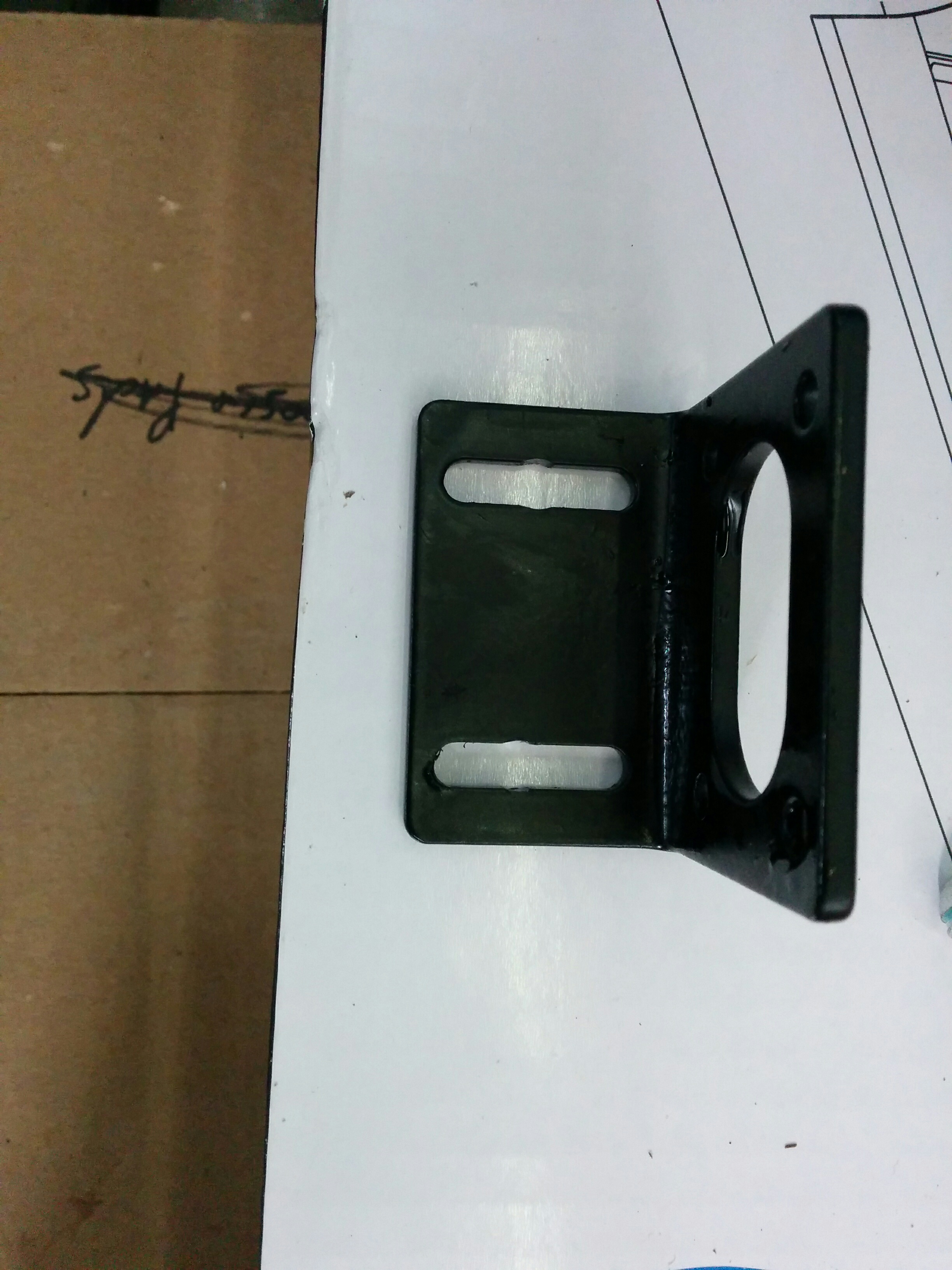
After building the frame for my Maslow CNC machine, the rest of the setup was just a matter of assembling all of the pieces. I used 1/4-20 “superstrut” nuts and 1/4-20 machine screws to mount the motor brackets. The slots in the brackets are almost, but not quite wide enough to let 1/4-20 screws go through them, so I had to drill them just slightly larger in the two spots I mounted the screws.
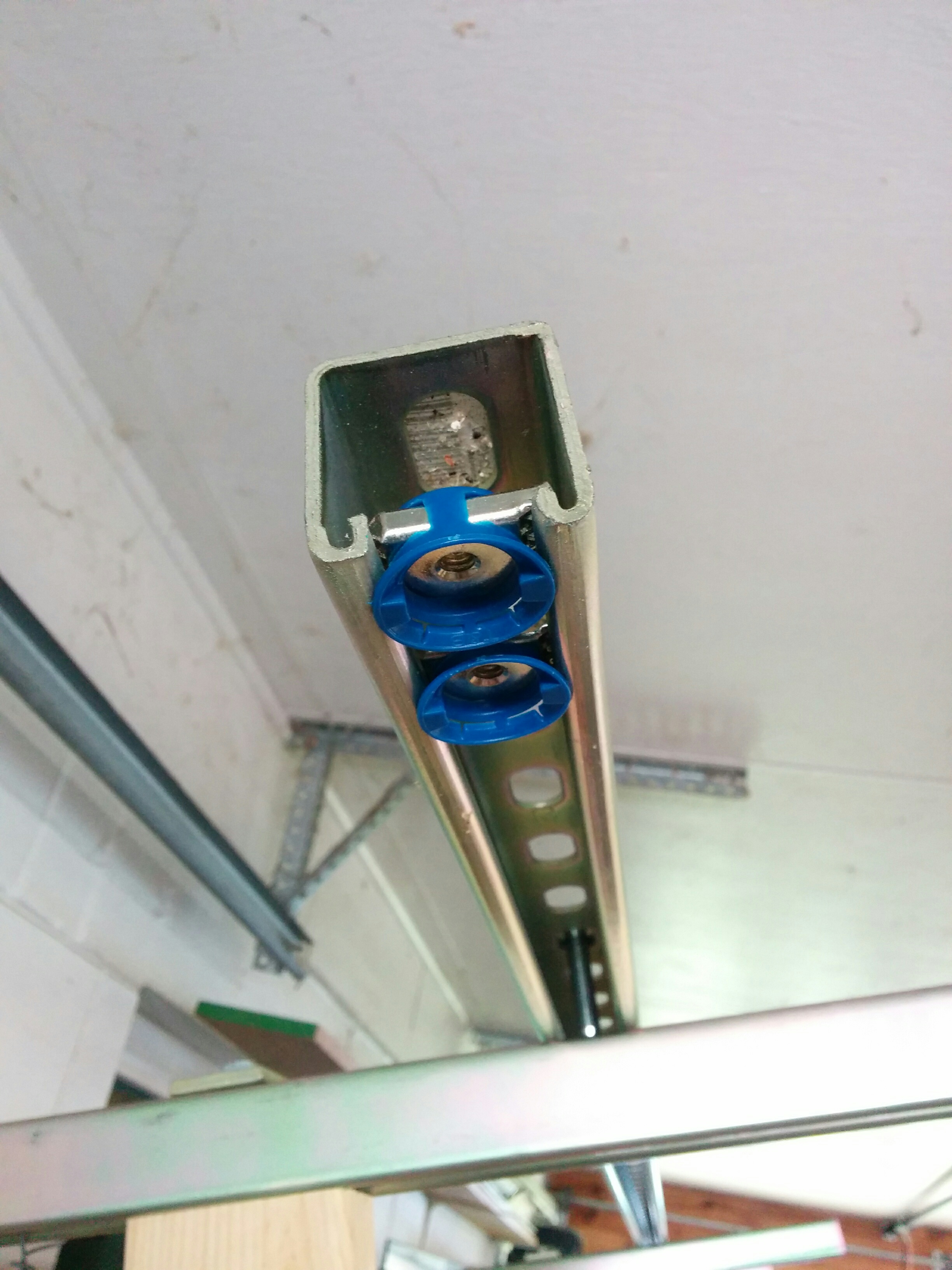
I made use of one of the four motor mounting holes to place an extra long (60mm) M4 screw holding a plastic idler that keeps the chain wrapped around the sprocket to avoid chain slips under tension. I’m currently using a binder clip to keep the plastic idler from “crawling up” the screw and eventually letting the chain fall onto the screw.
I considered buying a shorter screw to keep the plastic idler from crawling up the screw, but if I ever want to manually adjust the chain position on the sprocket all I need to do is remove the binder clip and slip the plastic idler up out of the way, so I’m leaving it as-is for now. I also paid Lowes an outrageous $5 for a set of two blue plastic end caps to make the end of my superstrut look nice.
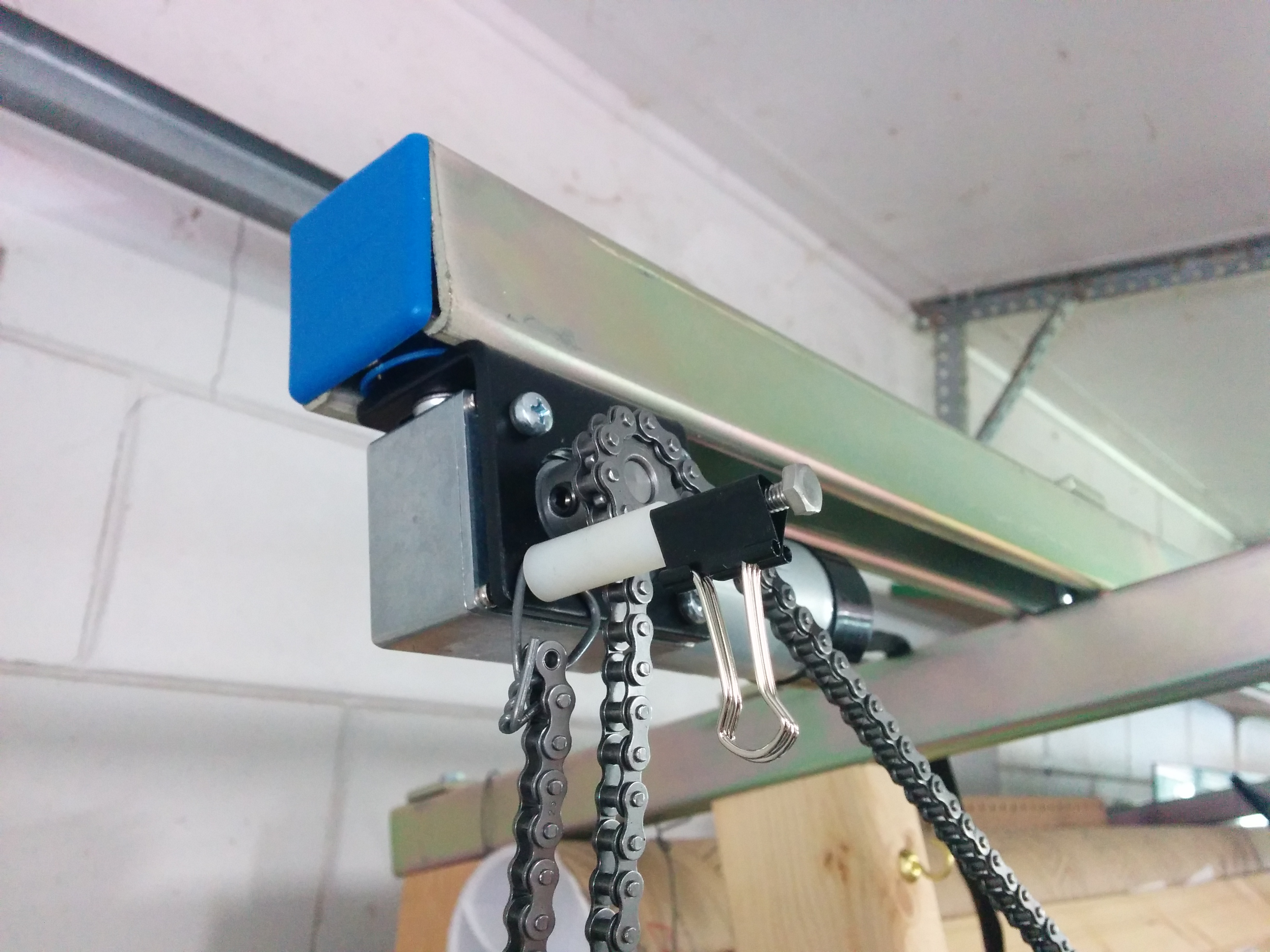
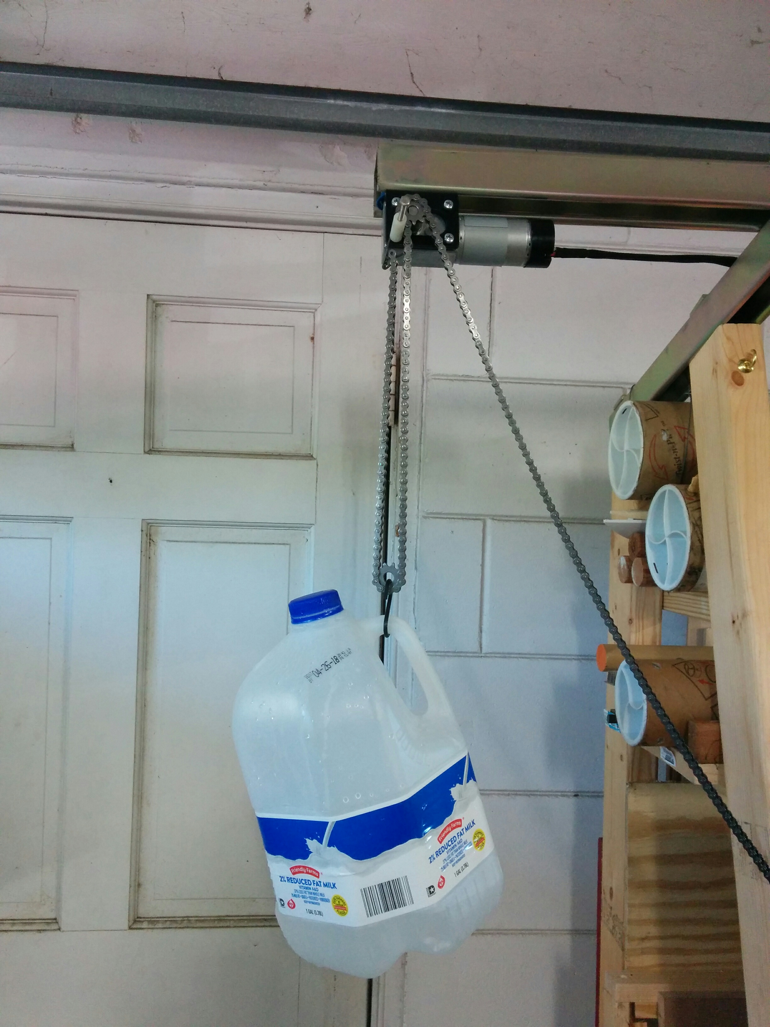
You can see that I also hung the far end of the chain from the idler mounting screw, and adjustable tension is placed on the slack side of the chain with an idler sprocket weighted down with a few pounds of water. (So far I just put a few inches of water in each jug, and haven’t needed to add significant weight.)
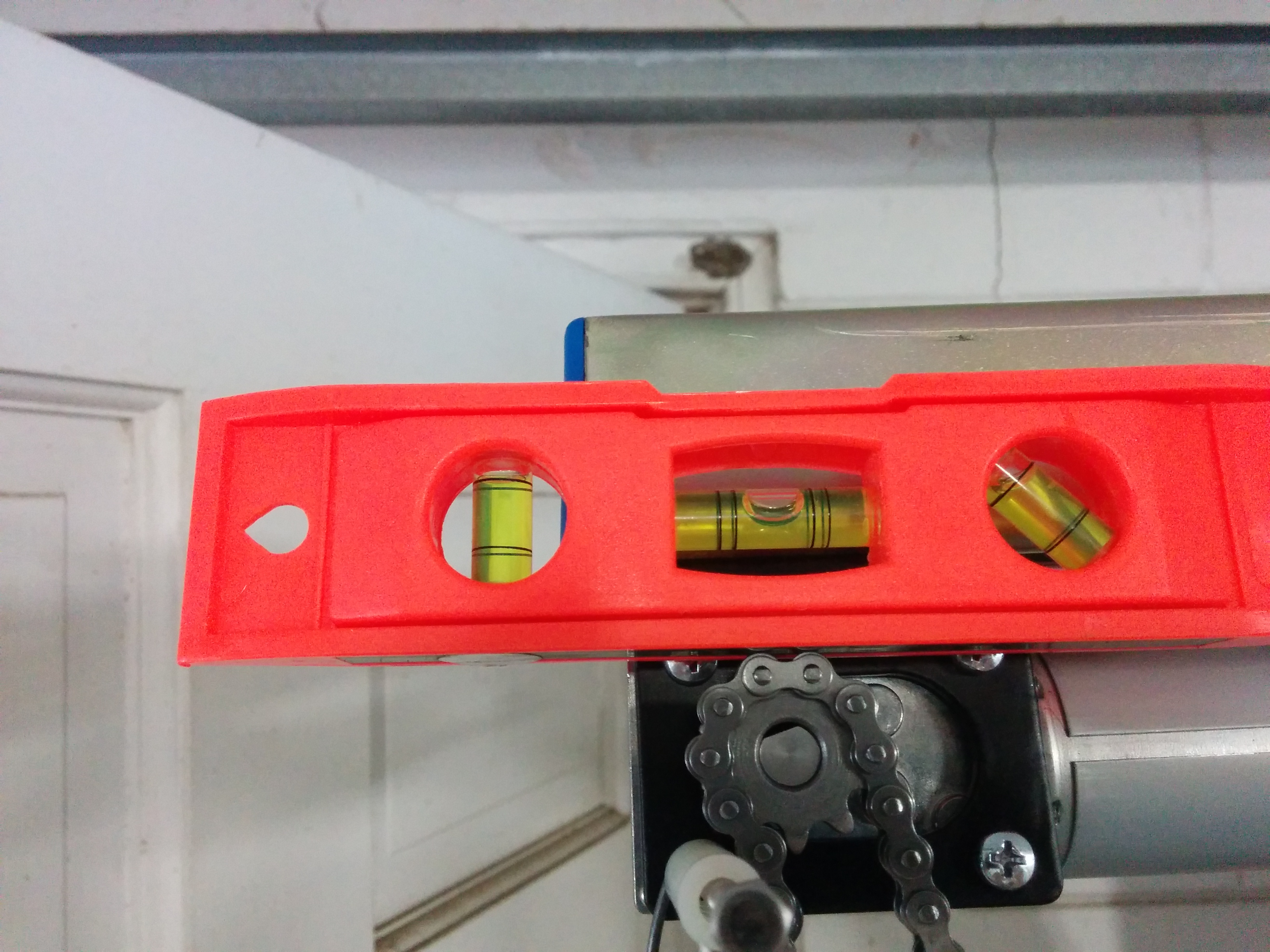
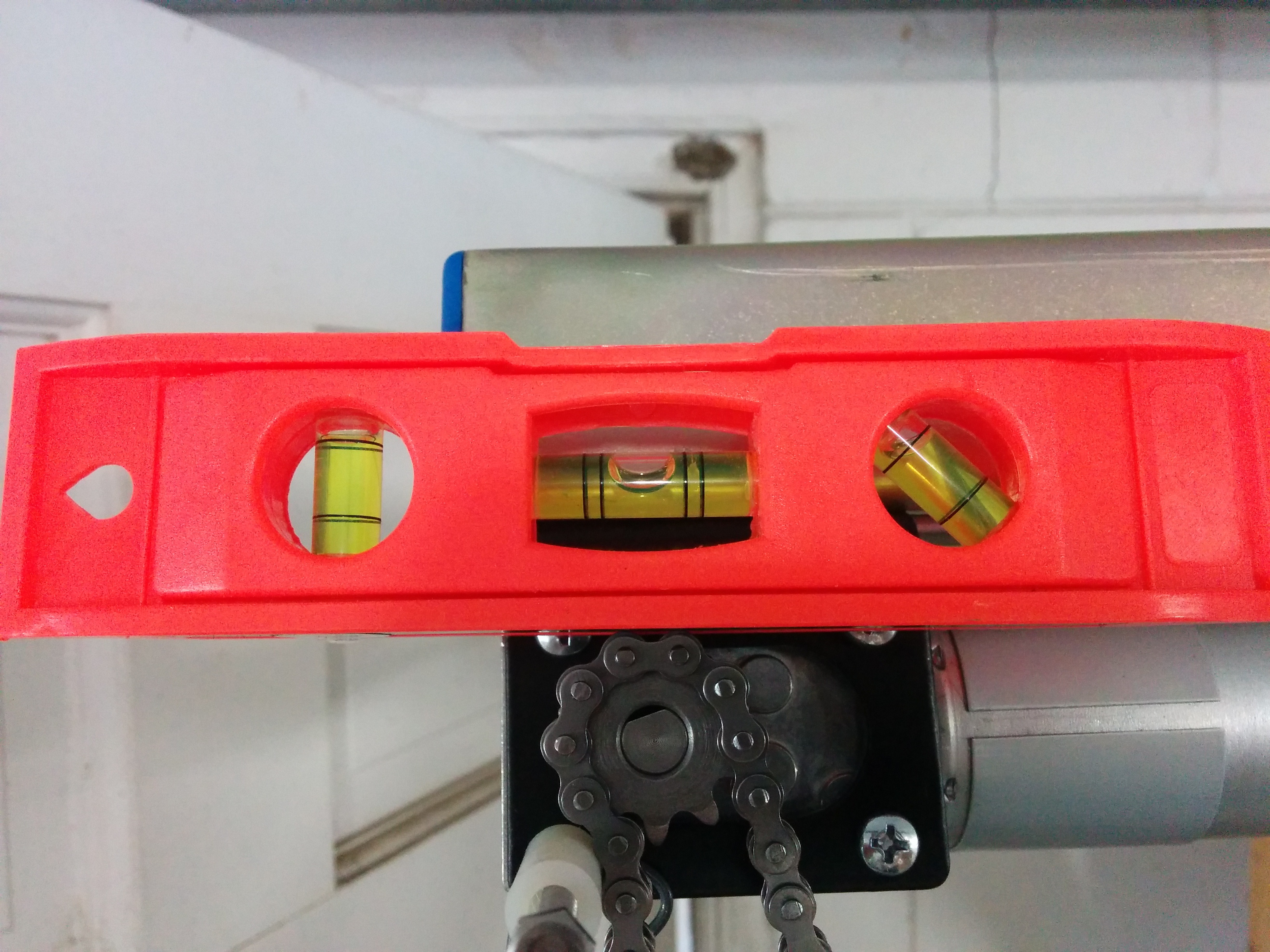
I found that I could balance a small level directly on top of the chain and use the bubble to get a tooth of the sprocket aligned vertically within a 10th of a degree. (At least, there was a small but visible difference between the bubble between presses of the 0.1 deg button in the software…you’ll probably have to click the photos to zoom in before you can see it…)
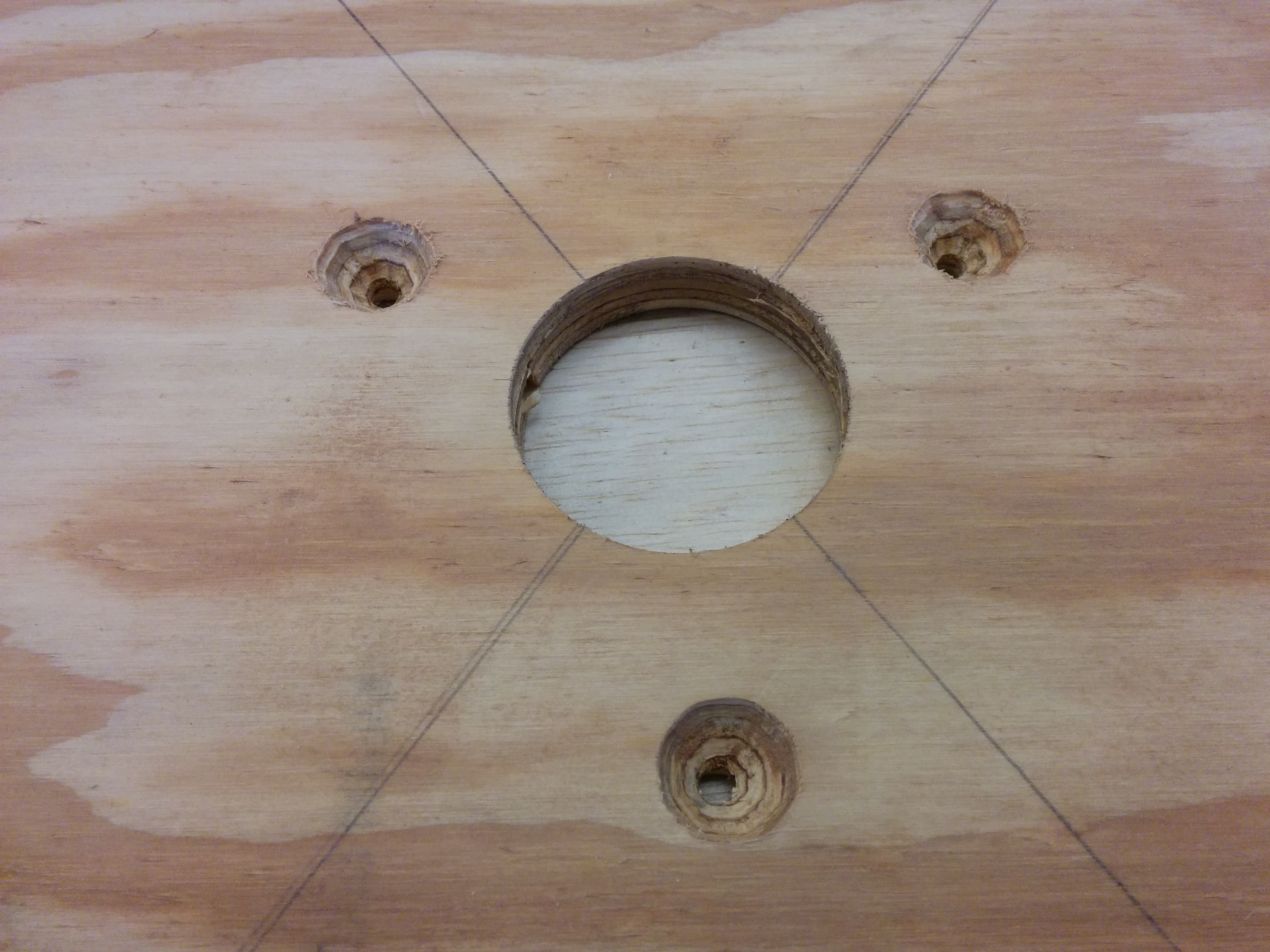
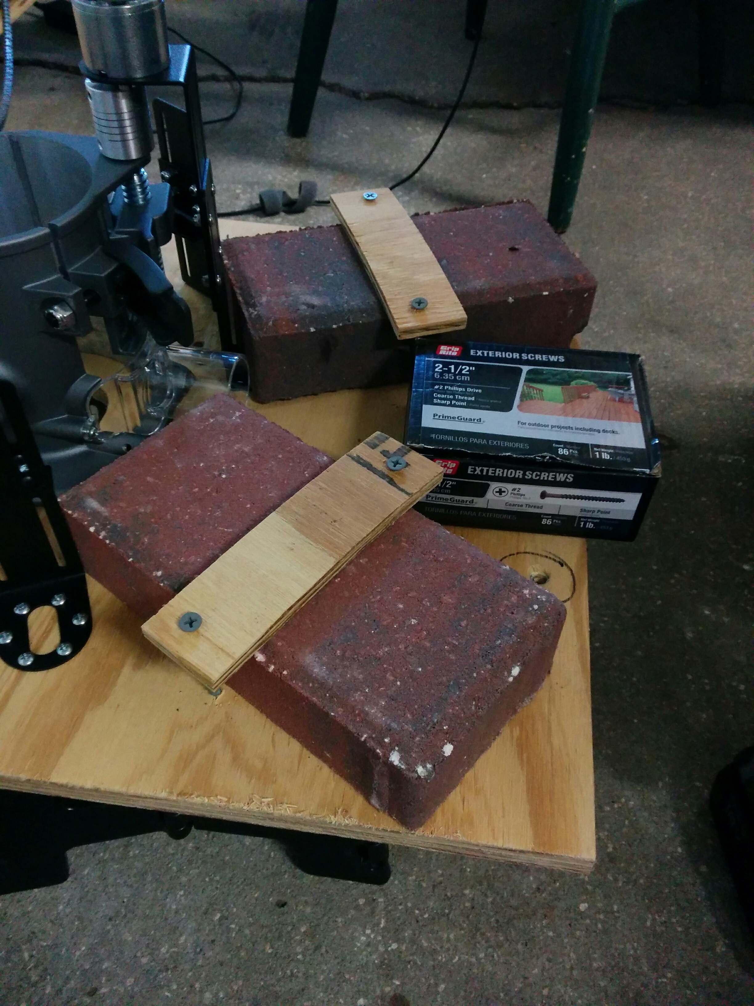
I built a temporary sled out of a piece of plywood that was left over from covering a window during Hurricane Irma. Instead of bothering to countersink the heads of the provided brick mounting bolts, I just used deck screws to mount the temporary bricks. I also was able to use the (too short) screws originally meant for the clear router base to mount the router to the plywood by abusing the heck out of a large countersink bit to REALLY countersink the screws so the short length was no longer an issue.
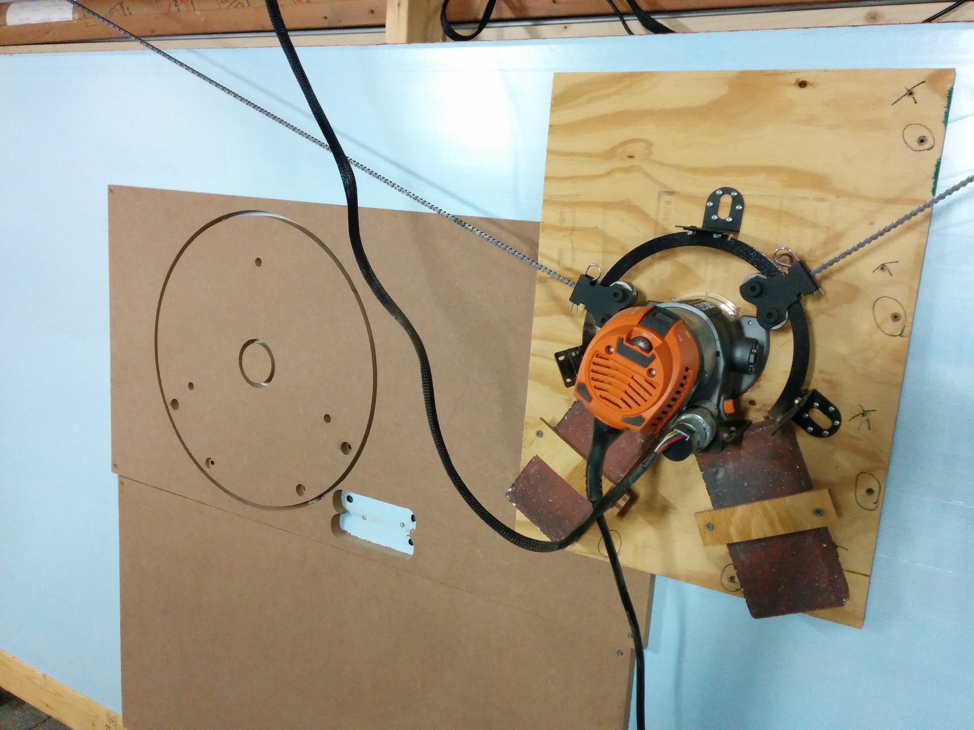
After calibrating the machine using the foam waste board, I used the temporary sled to cut a fancy round sled out of some MDF I had laying around. I don’t like the super fine sawdust that MDF generates, but it is more slick than regular plywood, which I figure is a good property for a router sled to have. (Plus, already had it laying around….)


Well done and thank you for your contribution . Keep it up!
Hey Jay!!! I’m trying to set my maslow up and I’m curious how you decide on where to place the 10′ unistrut across the top?
I placed it such that the motors would be in approximately the same location as the “top bar” in the official design.
As far as “in/out”, I set it up so that the cogs for the chains would be the same distance away from my work pieces as the “ring” that the ends of the chains roll around on the sled, so the chains are parallel to the work sheet and about 3″ above it.
Because it is bolted to the three small pieces of unistrut I can change the “in/out” amount if I need to depending upon the thickness of what I’m cutting, but so far I haven’t needed to adjust it that way.
Hey, I really like this design, and am going to imitate it I think. Do you find you ever moved the in/out distance?
I was thinking of using wood instead and make it non adjustable for now.
No, so far I haven’t had to modify it.
Just completed building out the frame you posted! Now I am onto this tutorial.
When mounting the motors on the unistrut, did you keep them on the very end? I was comparing the images above to the standard M2 build and it shows the motor mount should be 6″ away from the first triangle.
In addition they have the motor mounts on top of the beam rather than the bottom. I have never used this machine so I don’t know if that actually matters. (maybe it will be more obvious once I complete it all)
here’s the standard m2 build link so you dont have to hunt it down
https://cdn.shopify.com/s/files/1/0555/9903/8630/files/Standard_Frame_Guide.pdf?v=1644446882
My motors are 10′ apart (at the ends of the 10′ unistrut) This is the same distance in the m2 frame design (10′ board) but in the m2 design the triangles appear to be farther apart (note the 4″ gap in the middle as well), so they are closer to the motor. [The strength of the steel unistrut allows me to get a 1′ extension / cantilever, although you could certainly make my frame triangles wider. I just used the 4×8 plywood sheet as the end points of the triangle for simplicity, which is closer in design to the m1 reference frame.]
I believe the motor height between the top of my work piece is similar to that of the m2 frame, as I *think* the unistrut is mounted a tad higher than their wooden top bar. If you find the motors are too low (they worked fine for me) you could always just rotate the unistrut and bolt the motors onto the top instead.
sounds like you have answers to my questions. 1. how much did you counter sink (depth and diam) the router mounting bolts? and 2. how is the mdf holding up under use? I was concerned it might wear excessively.
They were more like “router mounting machine screws” with a 60 degree flat head, so I didn’t countersink them so much as just use a chamfering bit to chamfer out the hole. I pushed down a little hard so that the heads of the screws are about 1-2mm in from the surface of the MDF.
I haven’t really used my Maslow too frequently, but it held up just fine cutting out a LOT of ribs for my Christmas tree ball, no real wear to speak of.
https://www.summet.com/blog/2019/01/06/megatree-ball-topper/