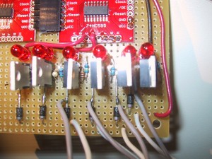
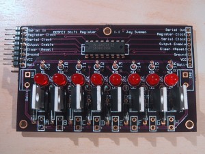
My BubbleDisplay project needed to control sixty DC motors or solenoids to control air injection into individual columns of liquid. Due to the large number of outputs needed, I am using a chain of (74HC595) serial shift registers so that three I/O pins can control all sixty outputs. As each serial shift register has 8 outputs, this requires eight chips (for a total of 64 outputs, four are unused). The 74HC595 can not source/sync enough current to drive the motors/solenoids directly, so I am using a TO-220 N-Channel MOSFET rated at 60 volts and 32 amps (digikey: FQP30N06L-ND) to drive the load, with an 1N4001 rectifier diode to handle current spikes. Because I had to make 8 (9 for a hot spare) copies of this circuit, I decided that fabricating a printed circuit board was the only way to go.
It only took me two tries (Moving from Version 1.0 to 1.1) before I was happy with the design, which you can see (populated for testing) above. Looks a lot nicer than the prototype, right?

I used the open source KiCad EDA software suite for the schematic capture and board layout and was quite happy with it. (Be sure to go through the Tutorial if you are just getting started!).
If you want to make yourself a copy, you can download the GERBER files that I used at OSHPark to make yourself a batch:
shiftMosfet_oshPark_1.1
I am also posting my entire KiCad project directory in case you need to make changes:
shiftMosfet_1.1_kicad
The parts needed to populate (one) board (with digikey part numbers) are as follows. Listed prices are for quantities large enough to populate at least 8 boards:
1 74HC595 IC 8-BIT SHIFT REGISTER 16-DIP        $0.63		digikey.com	296-1600-5-ND
1 CONN FEMALE 8POS .100" R/A GOLD               $0.767		digikey.com	S5483-ND
1 CONN HEADER 8POS .100 R/A 15AU                $0.333		digikey.com	609-3321-ND
8 MOSFET N-CH 60V 32A TO-220                    $0.94		digikey.com	FQP30N06L-ND
8 1N4001 RECTIFIER 50V 1A DO-41                 $0.1184		digikey.com	1N4001DICT-ND
8 RES MF 1/4W 10K OHM 1% AXIAL                  $0.0394	        digikey.com	S10KCACT-ND
8 LED SS 5MM 625NM RED DIFF	                $0.0932		digikey.com	754-1264-ND
8 RES 560 OHM 1/4W 5% CF MINI                   $0.0228		digikey.com	S560QCT-ND
The right angle (R/A) headers allow you to daisy chain boards next to one another, but you could omit them and connect the boards using hook-up wire (not recommended for a large number of boards…) You may note that with the exception of the extra BATT + connection (allowing the MOSFETS to switch a voltage higher than logic level to the outputs) the connections are in the exact same order as SparkFun’s 74HC595 breakout boards so you can daisy chain them together. Although the 8 pin header has a BATT+ connection, if you are switching large currents you should also connect up the extra large GROUND and BATT+ pads with larger gauge wire. You could also NOT daisy chain the BAT+ connection and drive each board or set of boards from its own supply.


Pingback: 22 of 60 tubes running – First scaling up problem rears it’s ugly head. — Jay’s Technical Talk
How much current do you think the PCB can handle? I need something like this to drive 12V LED strips.
The limiting factor is probably the MOSFETS (specifically, how much of a heatsync you can mount on them). They are rated at 32 amps with a full heat sync. Although if you are driving the whole thing above 10 amps you may need to enlarge the circuit board traces to handle the extra current.)
Dear Sir
Congratulations the project you did. This project will be my first arduino project .
I carefully investigated your videos and your blog. I will make Serial Shift Register MOSFET driver (version 1.1) PCB s but and I could not find the arduino uno sketch and circuit diagram for connections. I will also use 60 air pump. I will be gratefull if you share with me. Thanks.
You can find the BOM and source code on this post:
https://www.summet.com/blog/2013/09/01/bubble-display-source-code/
Hello Sir
At last finished the project and the only thing we need is shifter library. Can you share with us because we could not find it. Thanks.
The shifter library I used was created by Adam Meyer of bildr
http://bildr.org/2011/08/74hc595-breakout-arduino/
Although many other people have built similar libraries and explanations of how to build your own.
https://www.arduino.cc/en/Tutorial/ShiftOut
Hi Jay
I have the source code but i dont know the arduino uno s which legs will be connected to which curcuit inputs you designed (Serial Shift Register MOSFET driver (version 1.1)) .Thanks.
I’m afraid that I do not have a circuit diagram for this project. It is a relatively involved project, and I would not advise it as your very first project. That being said the circuit wiring is relatively simple. The source code specifies which pins go out to the RGB led’s and which pins go out to the serial shift MOSFET’s. Of course, you will also need to provide the appropriate (12v for the motors and 5v for the LEDs) external power to each device. I would recommend that you work with a single shift register (use the LED’s on it to get used to programming it before connecting any real motors) and a single strand of RGB LED’s to make sure you have all the signal wires connected correctly before trying to add more power/motors/leds.
These links will help you learn about the circuits:
https://www.arduino.cc/en/Tutorial/ShiftOut
https://learn.adafruit.com/digital-led-strip
I think I will start with one single shift register.Thank you for your advise and quick reply.
Hi. I am trying to open your schematic in Kicad (shiftMosfet.sch) but it complain about 2 missing libraries. Any chance you could provide links to the dependencies lib ? or maybe thoses libs aren’t really used by your schematic.
The missing libs are : diy_transistors / special
Thx in advance.
You can use the following specialized search engine to find various component libraries for kiCad:
http://per.launay.free.fr/kicad/kicad_php/composant.php
Searching for “diy_transistors” gives the following URL:
http://vkoeppel.free.fr/files/diy/kicad_diy_libraries.zip
This link about installing libraries may also be useful:
https://code.google.com/p/opendous/wiki/KiCADTutorialAddingLibraries
Can also PWM outputs?
Yes, you can PWM the outputs, but the PWM frequency is (much) slower than with a dedicated pin. And every time you add more outputs to your serial line, the speed at which you can PWM them goes down. I wasn’t having any problems turning individual pins on or off with 1-2ms accuracy, so PWM up to 500 Hz would be possible (if my Arduino did nothing else).
Instead of using PWM to control the motors, I just turned the “weak” ones ones on a few MS earlier than the “strong” motors to get all the bubbles to be the same size.
HI HELLO
nice job ….
how do i get to the layout of the pcb board .to change the name logo on the board…if im to copy your pcb layout
Search for this sentence in the post above blog post to download a zip file of all the design files:
I am also posting my entire KiCad project directory in case you need to make changes:
shiftMosfet_1.1_kicad
hi jay….
im having a little trouble adding your sketch to the arduino …
it says…. fatal error: shifter.h no such file or directory found…
#include
i tried uploading it to both …… libraries (no joy )
could you tell me a way i could get round this problem please….
thank you
The Shifter.h file controls the 74HC595 shift registers. I don’t exactly remember where I got that library from, but this link may be it:
http://bildr.org/2011/08/74hc595-breakout-arduino/
Hello, do you have these boards for sale? I need 12 units ready to play.
I’m afraid I don’t sell them, but you are welcome to use the files provided to have the PCB’s manufactured and build some yourself.
Jay – really appreciate you putting this out there. I’m trying to control a system to scare away turkeys at our organic farm, and this is much better than my board. Question for you though – what’s with the 4mm spacing on the final output connections? Did you have a connector in mind for that?
If you mean the high current output that drives the motors, those are designed to have through hole wires soldered directly to the board, you may need to change the spacing for connectors.
Hi Jay, I have a question about the MOSFETs, I am currently working on a project of driving 12v lights with an Arduino based on inputs it gets, and the max current these would pull is around 1.2 amps. I was previously looking at using STP16NF06L MOSFET’s, however the ones you are using have a higher Safe Operating Area. Would I still need to have a heat sink for this amount of current, and should I go with these MOSFETs instead of the ones I was originally going to choose?
Thanks.
1.2 amps X 12 volts = 14.4 watts draw. The STP16NF06L’s have a TYPICAL RDS(on) = 0.07Ω so your MOSFET would be dropping ~ 0.084 volts at 1.2 amps or 0.1008 of a watt as heat.
Assuming you are not switching them on/off a lot, you can probably use them without a heatsync.
(The MOSFETS I used have a typical RDS(on) at 10v of 0.027, so slightly lower heat dissipation and only cost 0.05 more each, plus have a much higher total amp rating (if that matters for future proofing), but I think either choice would work fine for your application.)
Thanks Jay, one more question, will a rectifier diode still be needed since I am just driving lights instead of motors?
Not unless your lights / light power circuit has a large amount of inductance….on the other hand, diodes are cheap to include just in case somebody wants to use the circuit to power something else in the future.