I spent a lot of time last summer and fall building this 62″ wide bubble display. So much time that I didn’t get a chance to edit together and post an “overview” video showing the whole thing in action. Well, here is that video. If you are looking for more build details just read all my posts tagged with “Bubbledisplay”. If you just want to sit back and watch the whole thing come together via videos, start watching my “BubbleDisplay” channel on YouTube At the beginning.
Tag Archives: bubbledisplay
Bubble Display Source Code & Bill of Materials
This open office / libre office / open document spreadsheet lists (most of) the parts I purchased for the bubble display, as well as the supplier part number. As some of the parts were surplus, or purchased from China via ebay, the suppliers may or may not still have them available. I didn’t keep the BOM document entirely up to date after I started to put things together, especially for several last minute runs to the hardware store, but it generally shows all of the major components.
Bubble Display BOM
This is a source code dump that includes the arduino code that I wrote for the bubble display. It’s not very nice looking, but it may help others to learn what I did on the software side of things. You’ll also need a Shifter library for the 74HC595 shift registers and a WS2801 library for the RGB serial LED string.
The “images” are encoded as individual pixels, hard coded as an array, generated by python code from simple .GIF images. Edit the image in an image editor, and then run the code to generate the C code array data.
Finishing the trim pieces
I am finishing up the trim pieces for the bubble display. The last component is the top cover that will hide the top of the acrylic tubes (and hopefully keep bugs out of them!).
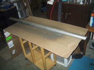
I cut the side off of a piece of 2″ PVC pipe and notched the ends to fit over/around the vertical end support and various mounting hardware. Then I used a universal metalic spray paint to give it a metalic look. Unfortunately, they didn’t have “alunimum gray” as a color option in spray paint that works on plastic, so I had to go with “Satin Nickel” which has a subtle bronze/gold tint to it. I’ll try it on the actual bubble display and if it doesn’t match closely enough I can always use it as my plastic bonding base coat and paint over it.
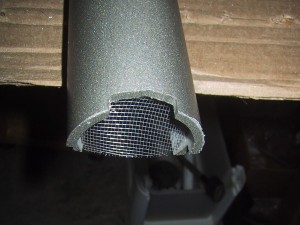
I used high temp hot glue to affix bright aluminum screens into the ends of the top piece, which will hopefully minimize the incidents of insects trying to get a drink and falling into the tubes. Admittedly, this may be a bigger problem in my not terribly well sealed garage than the office building where the bubble display will live…but it doesn’t hurt, and it also makes the ends of the cover look more professional.
Text on the Bubble Display
The text of the logo is recognizable even in water. With glycerin I think it will be even nicer looking.
I’m actually cheating by rendering text as a bitmap image and then using software to load the bitmap into the arduino. So really, this is a video that demonstrates my ability to display arbitrary graphics, not actually generate text. (But I do plan on embedding a simple font table in the arduino so that the arduino can just render generic text.)
Bubble Display Frame Trim
Now that I have the electro-mechanical systems working, I am focusing on finishing the trim pieces for the frame that will hide the electronics and top of the tubes.
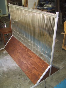
This mostly consisted of notching a few slots in the pieces of plywood for the aluminum bottom pieces and cables to go through, and a day’s worth of work with a spray gun.
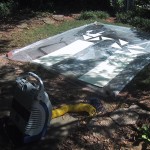
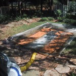
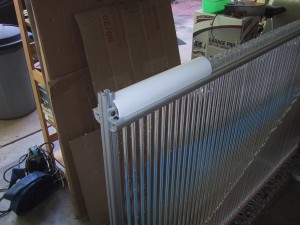
I had initially planned on using bright aluminum window screen mesh in a half tube shape over the top of the upright acrylic tubes, both to keep bugs out, as well as to give a nice visual appearance. But once I tried it out, I didn’t like the appearance, and couldn’t think of a good way to mount the ends of the screen cleanly. I am now considering using the old standby PVC pipe (probably painted some solid color with plastic spray paint). The other option is to buy a large clear acrylic tube (square or round) and use that in the same place. This would allow people to see the tops of the tubes (perhaps too well…it’s too bad McMaster doesn’t sell frosted acrylic tubes…) This is my current prototype:
Bubble display fiber optic relay
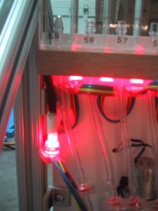
Because the air hose is connected to the center of each square acrylic tube, the 60 LED lights on the bubble display are mounted almost between tubes, very close to the left edge of each tube. This means that a particular LED contributes light to both it’s own tube, and the one to it’s left. On the far right side of the display this makes mounting the first LED easy, as it is well away from the outside aluminum support upright. However, on the far left side of the array, the hole for the LED is right up against the aluminum support upright. The LED’s have a square circuit board below them that makes the entire unit wider than just the LED, and it won’t fit.
I knew this would be an issue from the beginning, and had designed my way around it using a bit of fiber optics. Of course, the far left tube is slightly dimmer than the others…but then again, so is the far right tube (which only has one LED).
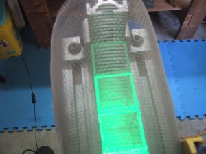
60 tubes working!
Yes, I finally have all sixty tubes mounted and working. I still need to swap out two or three of the under-performing motors, and calibrate all motors, and do a lot of cosmetic finishing work (cover pieces for the top and bottom), and some software tweaks….but it’s finished enough to actually work!
22 of 60 tubes running – First scaling up problem rears it’s ugly head.
Here is a video of 22 tubes running with water:
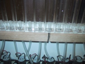
Now for the bad news….22 tubes actually measure 22 1/8″ wide. (apparently each tube is actually 0.00568 inches larger than 1″) This means my entire display would be 3/8″ too narrow, which just won’t work with the tolerances I have designed into my tube holder. That is why I only have 22 tubes in this video….the 23rd tube was just far enough off to not fit into it’s proper hole.
I fixed it by cutting the tube holder into 3 pieces and mounting them with a 1/4″ gaps between them.
I also had to space the end pieces of aluminum farther out, which meant I had to drill 4 new holes to mount the side brackets to the bottom board 1/2″ farther apart. Luckily the T-Sloted aluminum mounting system allowed me to easily move my L-Brackets up slightly to hit the new holes.
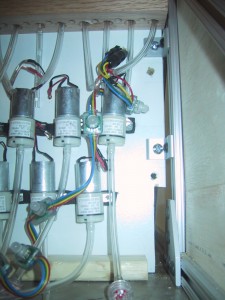
Unfortunately, I mounted the Shift MOSFET circuit boards on TOP of the screw heads holding the tube support board, so I had to take them all off to re-position the tube support board. Annoying, but not the end of the world.
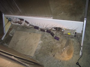
So, after a bit of additional work, I now have all 60 tubes working.
Electro-Mechanical systems complete
All sixty RGB LED’s and air pumps working under computational control. Next up, physical assembly.
Bubble Display update: 24 motors connected
Here is a video of the bubble display base with 24 (of 60 total) motors connected running a test pattern. Next up….lots more soldering. I’m very glad I was able to find strings of 20 RGB leds already connected!
