In part 1 of this series I got the stepper motors for the 3 axes moving. In part 2 I hooked up the home and E-Stop switches. In this post I will describe getting the spindle motor to turn on (and off!) controlled via the parallel port break out card (I’m using Pin 1).
You can watch the video here, or read the text and see the photos below:
To enable the spindle motor, two things have to be done. First, the Spindle Go Relay (SGR) must be turned on, which provides 120 volts AC to the spindle driver board. Second, the spindle driver board input needs a 10 volt input to turn on the output (to the spindle motor) at full blast. The photos below are of my Dispatch Date 2005 mill, but other mills from Denford are similar in their general operation. [If you have an earlier dispatch date mill, you may have a DIN rail of relays mounted individually instead of this custom PCB of relays. Check out this post for a few photos and info about the SGR in that situation.]
Spindle Go Relay (SGR)
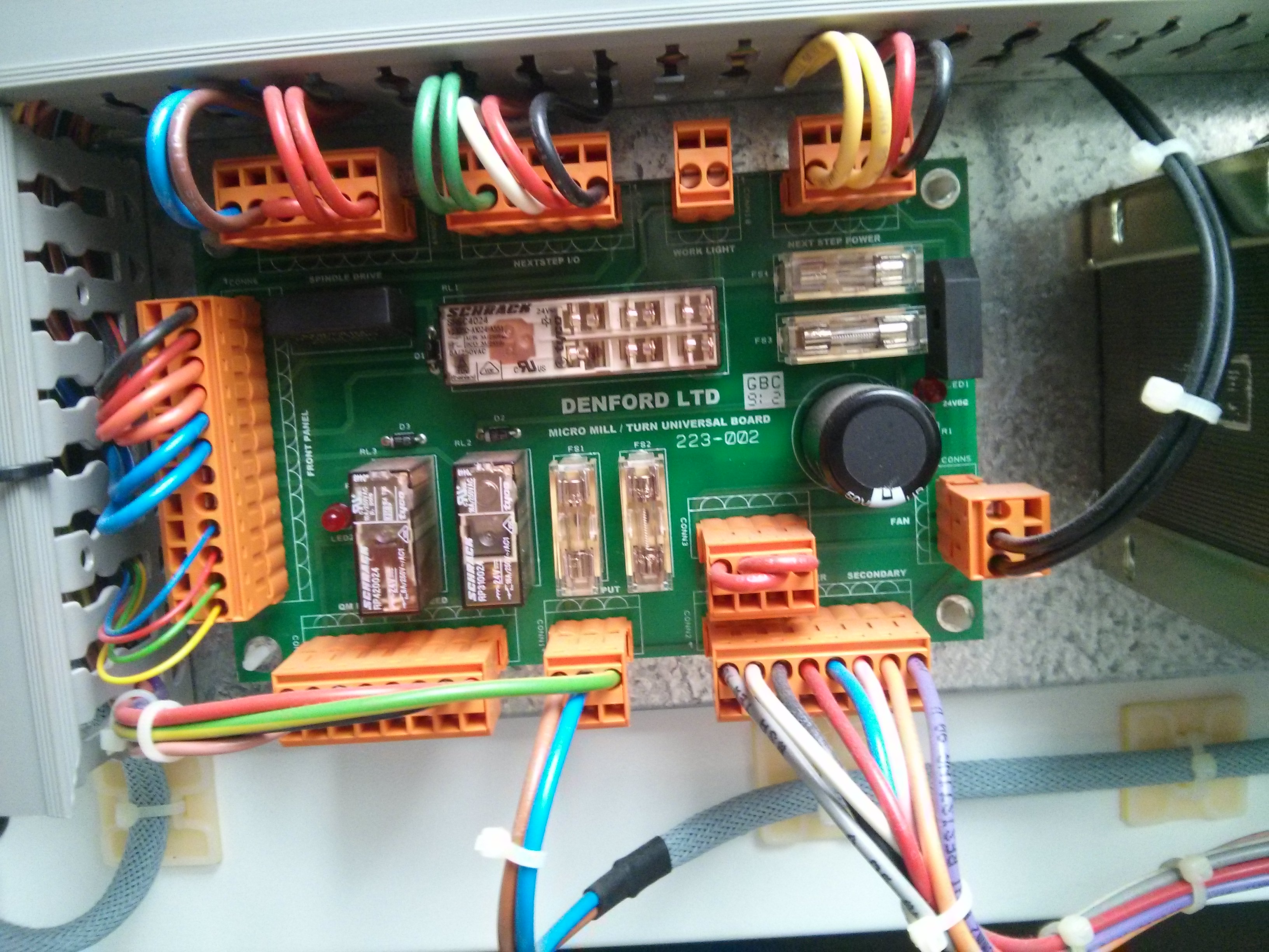
This is a picture of the main power distribution board. The large top white rectangle (just above the Denford LTD text) is the main E-STOP relay (R1). It will turn on only if the E-STOP system is not activated. Directly below it are two fuses, and below and to the left are two smaller relays. The center relay (R2) directly to the left of the fuses is the Spindle Go Relay. It’s coil operates on 24 volts DC (higher than 5V TLL, but lower than 120 AC!) One side of the coil is connected to the +24 supply via a magnetic guard switch that is closed only if the plastic door/guard is in the down position. (This keeps the spindle from turning while the protective door is open.) The other end needs to be grounded to activate the relay, and the connection from it connects through the large white wire in the center of the top center connector block with five wires (Green,Green,WHITE, Red, Black). This large white wire is connected to UserOUT-0 on the NextMoveST board, which is connected to pin C6 on the 96 way connector. In summary, connecting C6 to ground will turn on the spindle go relay.
Unfortunately, because the positive voltage is 24 volts, connecting C6 to +5 volts will ALSO turn on the spindle go relay, so you can’t just connect C6 directly to an output pin on your breakout board. Instead, you need to use the 0-5v signal from the breakout board to switch the current between C6 and ground. You could do this with a small 5v coil relay, but if you are not afraid of transistors, you should just use a NPN switching transistor in low side switching mode.

Here is my current switching “circuit” The yellow wire from C6 goes to the transistors’ collector. The blue wire from my 0-5V output signal (pin1 on the break out board) goes into the base via a 1K resistor which limits the current draw. And the emitter of the transistor is wired via the green wire to ground (on the break out board, which eventually links back to a GND pin on the 96 way connector). After I verified operation, I dead-bugged the resistor and transistor together so I could just screw them into the break out board terminals.


This allows pin 1 on my break out board to enable/disable 120 volt power to my spindle control board by controlling the SGR.
Spindle Driver Board

This is the spindle driver board, which takes in 120 volts AC, and outputs power for the spindle motor. It uses a 0-10 volt signal to determine the speed that the spindle should go. (This is open loop control as the spindle motor doesn’t have any encoders on it.)
In the photo above, the 120 volts AC that is enabled by the SGR comes into the spindle control board via the blue and brown wires that plug in at the top right. The power to the spindle motor goes out via the Red and Black wires (Red in the top left, Black in the middle right).
The two small red/blue wires in the foreground (plugged into the P2 and P1 0.250 inch blade terminals) are the 0-10 volt signaling wires from the NextMoveST board. (They are connected into the SOUT and SGND lines on the bottom left of the NextMoveST board.)
P1 is a 0 volt (ground) reference for P3 which is a 10 volt supply (actually closer to 11 volts on my board). P2 is the input for the spindle speed controller. If you want to manually control the spindle speed with a potentiometer, you just connect a 5K linear POT between P1 and P3, and connect the wiper (middle terminal) to P2. Turning the POT gives P2 a selectable 0-10 volt input signal.
However, I believe that the MicroMill had full PWM control of the spindle speed via the NextMoveST board. The SOUT and SGND output on the NextMoveST board is isolated from the rest of the logic signals, such that they can float to high voltages with the spindle board. So we can’t just connect P2 to an output pin on our BreakOutBoard to connect 0-5 volts to get up to 1/2 speed.
For now, I have attached a jumper between P3 and P2, which locks the spindle board to full speed output, and I turn it on and off using PIN 1 on my break out board that controls the SGR via C6.

This is not elegant, but for a Sherline mill, full speed is generally just fine. However, I really, really want to figure out how to control the SOUT output on the NextMoveST board. When I first started working on the spindle, the NextMoveST board was outputting an 11 volt signal on SOUT, so as soon as I enabled the SGR the spindle turned on full blast! This persisted for several on-off cycles, but eventually (right after I got the transistor control of the SGR working) it stopped putting out an 11 volt signal, which is why I had to jumper P3 to P2.
I have looked very closely at documentation on the 96 way connector, but I haven’t found anything definitive about if any pins on it can be PWM’ed at 5 volts TTL to control the 0-10 volt output from the SOUT pin. Worst case scenario I may have to purchase an isolated TLL/5V to DC 0-10 volt converter and bypass the SOUT circuitry on the NextMoveST board.
Update: Part 4 of the series shows how to get PWM control working (soldering directly to a chip on the board).


 interior photos")
Pingback: How to convert a Denford / ScanTek 2000 Micromill to LinuxCNC / Mach3 control: Part 1 – 3 Axis control | Jay's Technical Talk
Pingback: How to convert a Denford / ScanTek 2000 Micromill to LinuxCNC / Mach3 control: Part 2 — Home switches & E-Stop | Jay's Technical Talk
Any thoughts on why my + and – 12v DC outputs or not putting anything out? Checked the rectifiers and they seem to test ok.
It would depend upon where you are testing for power. I know that certain of the emergency stop switches and relays will shut down all power if they are dis/engaged. Confirm that you have turned on the keyswitch (which will make a relay click) and have the clear plastic guard down so that it’s sensor switch will register, and have turned the e-stop button to disengage it.
hey bud thank you so much for doing this. i have one and i did the change however it didt work for me. im sure is something im doing wrong with mach 3. i was wandering if you have the set up for mach 3 if you dont mined sharing it.
Ones again thank you for taking your time for doing all this.
I’m afraid that after I got the hardware working with Mach3 I blew away the windows partition on that laptop to install Linux CNC and have been using that ever since, so I no longer have the Mach3 config files. I do remember that I had to use the diagnostic window that shows the input/output level of all the lines visually (with green and red dots I believe?) to make sure that the e-stop and limit switch inputs were correctly set up before I was able to get the X/Y/Z axis moving.
Hi Jay.
First off, thank you so much for taking the time to document this conversion so thoroughly. I’m part of a makerspace an we recently got a Denford donated to us. We got the Denford software with it, but we already have a router that runs mach3 so for consistency sake we decided to convert it over.
I would like to let you know there is at least one more variant of the spindle control relay out there. My mill (an actual denford) does not have the relay board like yours, but instead has DIN rail mounted relays. So while everything else worked in this conversion I have yet to get mach3 to control the SGR. In the mean time while I figure it out, I’ve just changed the wring from the NO position on the relay to NC so the board always has power.
I’d be happy to get pictures if you’d like to include them on your website.
I also have the config file for mach3 if you’d like to make that available for people as well.
Sure, send me the photos, details of your mill (photo of the plate on the side?) and any config files and I’ll post them as a separate post to hopefully help others.
If anybody is looking for Cliff’s pictures and Mach3 config, you can find them here:
https://www.summet.com/blog/2017/09/23/denford-micromill-2000-january-2003-dispatch-date-sgr-location/
Jay, thank you for the write up on upgrading the Denford machines. I am accumulating parts to convert my MicroMill 2000 to parallel, but am not a huge fan of modifying the board to allow spindle speed control. I have been eyeing the CNC4PC C41 – PWM Variable Speed Control Board. If I understand correctly, I will be able to use this to control the spindle. Do you have any thoughts or reservations on using that board? Your assistance is greatly appreciated!
Thank you
Nick
Yes, that board is the easy solution and should allow you to interface directly to the motor control board. I just modified the driver board to use it in place of spending the $45 and adding a second board.
Hey – thanks for these videos and details – it is potentially a very cost effective conversion for me, however I have denford novamill. It looks like the baldor board is identical to yours however the spindle drive is not – I also cannot find a c10 parallel board in the UK – could you recommend any alternative?
Many thanks
I’m afraid I don’t have a specific recommendation for the UK market, but I’m sure there are various options out there. You can either go with a level converting board that allows your computer to drive the built in stepper drivers on the Baldor board and interface with the spindle controller….OR, you can buy a setup that includes the stepper motor drivers (and even spindle motor controller) onboard and just wire up the steppers/limit switches/spindle motor and completely replace the Baldor board.
Level conversion boards are cheaper as they don’t include the stepper drivers and spindle motor controller, but sometimes a complete replacement is actually easier to install. Just about any CNC controller will be able to handle the small steppers used on the Sherline mill.