In part 1 of this series I showed how to get the X/Y/Z steppers moving. In part 2 I hooked up the home and estop switches. In part 3 I got the spindle go relay working so that I could turn the spindle on (at full speed) or off. In this post, I will show how to get PWM speed control of the spindle working.
The Balfor NextMove ST card has an output (SOUT & SGND) line that provides an isolated 0-10 volt signal (at low current) suitable for controlling a spindle motor driver board. (0 volts is stopped, 10 volts is full power) In the bottom left of the picture below you can see the small blue and red wire leading away from SOUT & SGND.
It does this by using a DC/DC converter (NME0512D) to provide an isolated (floating) 12 volts, referenced to the SGND connector. A TLC272C OpAmp chip integrates a PWM signal (taking into account an offset adjustment from R35, the boxy blue variable resistor near the SGND/SOUT pins) into a 0-10 volt signal.
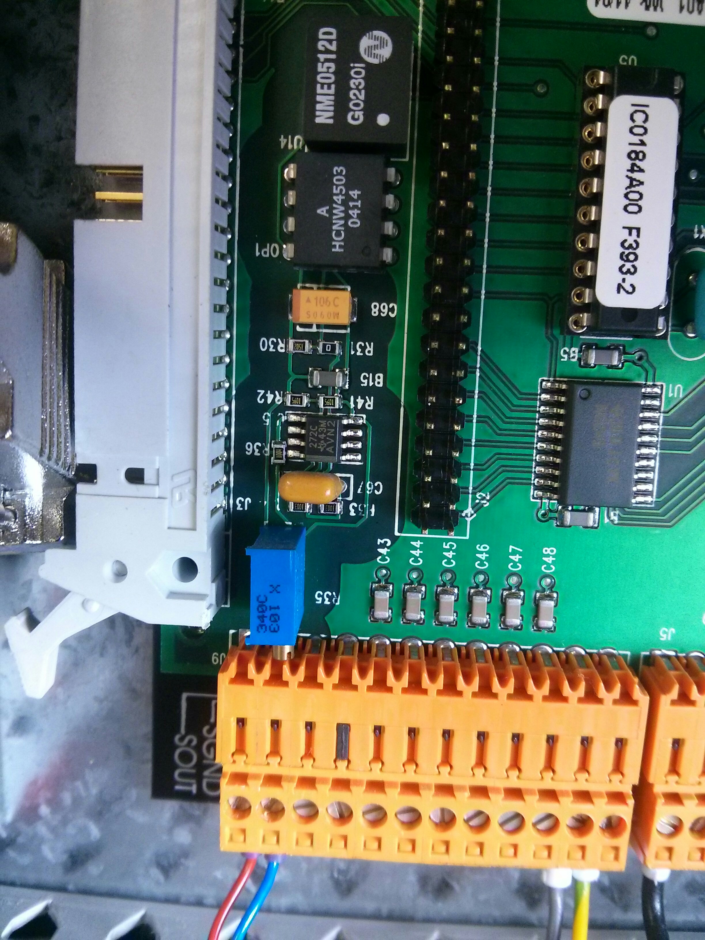
The PWM signal is fed via an Avago HCNW4503 optocoupler. Pins 5-8 are on the isolated output side while pin 2 is the anode (+5 volts) and pin 3 is the cathode (GND) of the LED inside the optocoupler that works at logic level with the rest of the Balfor board.
If you have to buy this circuitry on an adapter board it typically costs around $45-50, so I wanted to re-use it if possible. I was hopeful that the input to the optocoupler would be exposed on the 96 way connector (or the 50 way connector on the left side of the board) so that I could just plug into them. Unfortunately, this is not the case.
Pin 2 is tied directly to +5V, and the optocoupler is made active by grounding pin 3. Pin 3 does not lead to any external pin. I took the board off its mounting plate to try and trace where it did go, only to find that it was a 4 layer circuit board, and all the “interesting” traces were hidden on the inside.

Using my multi-meter in continuity testing mode, and 180 odd pins later, I finally got around to testing both sides of all of the surface mount resistors on the board and found that R29 (a 220 Ohm resistor) linked Pin 3 of the optocoupler to pin 12 of a big square IC surrounded by a white silk-screen box on the circuit board. It is a NEC 071054L-10 0417YKW37 a programmable timer/counter. Pin 12 is one of it’s output pins.

Basically, the top board would program this chip to output a specific PWM signal every time it wanted to change the spindle speed. (Requring 8 data lines plus several control lines….)
Since I was not going to be able to route a PWM signal via an exposed pin, I decided it was time to do some circuit bending. I removed the surface mount resistor R29 (disconnecting Pin 3 of the optocoupler from the programmable timer/counter chip) and soldered a 200 ohm resistor and a wire directly to Pin 3. (Covered in hot glue for strain relief….)

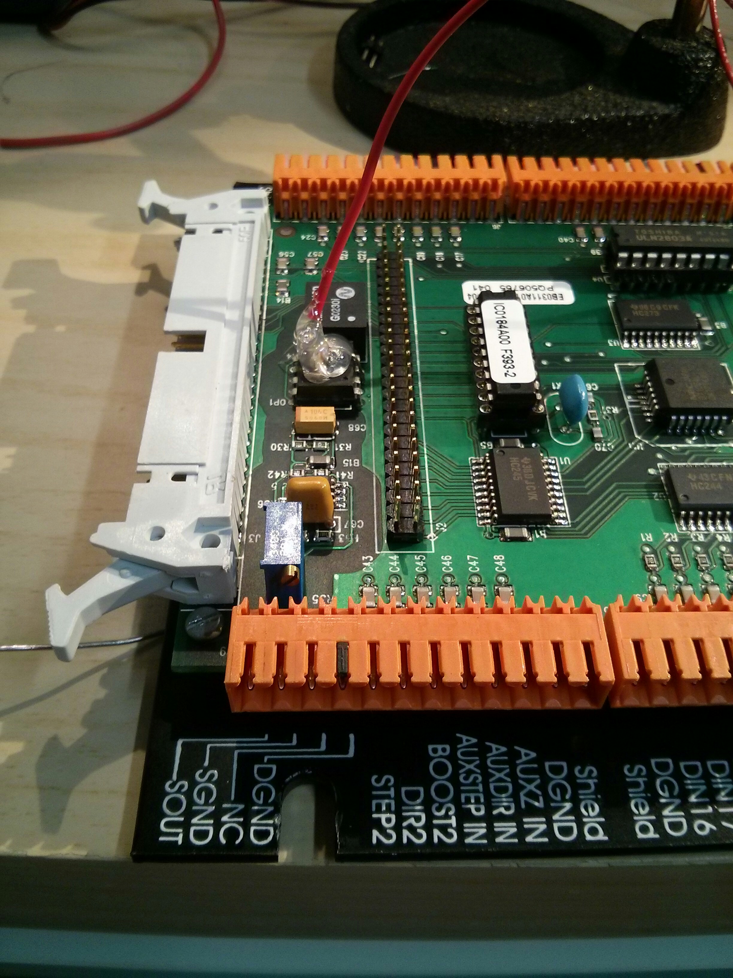
When this pin is brought low (inverted output) the voltage on the output climbs towards 11 volts (maximum power). I was able to plug this wire into my parallel port break out board pin 14 and using a PWM frequency of 100 Hz my LinuxCNC software is now able to control the spindle speed.
I now have software control over all aspects of the Sherline CNC mill in my Denford / ScanTek Micromill 2000. (Replacing the proprietary top board with software control via the parallel port.)
I’m mostly done, and plan on beginning work on the ScanTek Lathe that I purchased at the same time. Hopefully, now that I know what I’m doing, things will go much faster! Future improvements to the mill may include the addition of a “touch-off” plate/sensor and a spindle speed sensor for closed loop spindle speed control. I am also working on fixing a bent spindle motor bracket.

 interior photos")


Pingback: How to convert a Denford / ScanTek 2000 Micromill to LinuxCNC / Mach3 control: Part 1 – 3 Axis control | Jay's Technical Talk
Pingback: How to convert a Denford / ScanTek 2000 Micromill to LinuxCNC / Mach3 control: Part 3 — Spindle Motor Control | Jay's Technical Talk
Just spent the last two days studying this series along side photos of my machine and will be making the same conversion. Thanks for taking the time to lay this out!
Glad the information may help someone!
Great article, do you know if the circuits you used are the same on other mills ?
Emgee
If it’s a denford or micromill from the same general year model they will be exactly the same. I don’t know how far before/after the year 2000 they didn’t have any changes, but from my online reading it appears that they used the same basic control board for quite a few years with minor changes (upgrade to USB, slightly different safety switches, etc), so most of the details should be very similar for quite a few Denford/Micromills.
Hi, do you know if this same mod would make the spindle speed controllable through Mach3?
Yes, I actually used Mach3 for testing while I did the modifications, and then switched over to LinuxCNC.
It’s just taking a parallel port pin and using it for the PWM signal, so any software that can do PWM on a parallel port pin will be able to control the spindle speed.
Could I just close the magnetic reed switch and use the pwm spindle from there. Also, how is your spindle configured in cnc linux?
If you hotwired the spindle speed control you could run it at full speed without connecting the PWM pin for programatic speed control.
I have it configured to work between 20% (minimum speed, 70RPM (a guess)) and 100% PWM (2500 RPM, another guess) for full speed. I believe I was using 100ms pulse widths (spindle carrier 100) . I used Pin14 for the PWM control.
I just recently purchased one of these used in the classifieds and am about to do this conversion as well. Thanks for the write up. Very educational.
Jay, finally got a couple of days off and finished the conversion to parallel port control with Mach3 and PWM speed control. Just got to tune now. I’m very grateful for you taking the time to put together and post the conversion process using the existing control board. I was originally going to scrape out the Baldor stuff and use different drives. Save’s a lot of time and money.
Next up is the Scanturn. From what I’m reading I won’t be able to use the existing encoder, but I’ll cross that bridge when I get there.
Keep up the good work!
Glad you got it all working and that my post was helpful, it took me a few months to figure out the PWM circuit board hack.
I didn’t have an encoder on my Lathe, so I didn’t work on that problem, but I suspect you COULD make it work with a parallel port break out board, it’s just a matter of figuring out where in the circuit to grab the signal and how to get it into the BOB.
I’ve completed the process to get the steppers to move. I am a little confused on how to get the spindle to come to life. Currently I have it hard wired and it just runs at 1 speed. I didn’t use a bob. Only used a db25. Could you be kind enough to share some of your knowledge. Thanks in advance
Hi Jason,
Everything I know about getting speed control on the system is outlined in the above video and text. Having the motor hard wires to run at full speed all the time is a good solution, as speed control isn’t really necessary.
I would like to use the potentiometer on the front of the machine and run the spindle as a stand alone item,can I do this with out the 10 volt input you mentioned?
Check your spindle control board. If it has three terminals labeled P1, P2 and P3, you can attach a potentiometer to them and use it to control the spindle speed. On my machine, if you connected P2 directly to P3, the spindle motor would run at full speed.
If you wired up the pot between P1 and P3, with the “wiper” of the pot (center jack usually) to P2, you should be able to select between 0 and 10 volts (0v on P1, 10v on P3) and direct a specific amount to P2 (the control input).
Hi Jay,
I’m trying to figure out if I can control the spindle speed using the GRBL board I am developing. You mentioned that you set the PWM frequency to 100Hz. Do you know if another frequency (say 1kHz) work as well?
I appreciate all the information you have shared. It has been very helpful.
-Jonas
Hi Jonas, I’m afraid I don’t know for sure. I believe it is a 0-10 volt signal, and the PWM is just a way to get to a specific voltage, so a 1 kHz PWM is also likely to work, although you MAY need to add a small capacitor in the circuit as a buffer.
That makes sense. Thanks for your quick reply Jay!
Hi Jay,
This article helped me get my micromill up and running a few years back. Ive since dug the mill out of storage and I will be adding pwm control as well as switching from mach to linuxcnc. Did you ever get around to adding a touch off probe as well as closed loop spindle control? Is it worth keeping the baldor/bob setup to add touch off and closed loop spindle control or should I look at a different route?
Thanks,
Never set up a touch off probe or a RPM sensor, but if your break out board has an extra two inputs (one for the RPM sensor and one for the touch off probe) it should be easy to set up without involving the baldor board at all.
That’s excellent. Thank you
Thanks for this info, will be using the pin out to get my machine running!