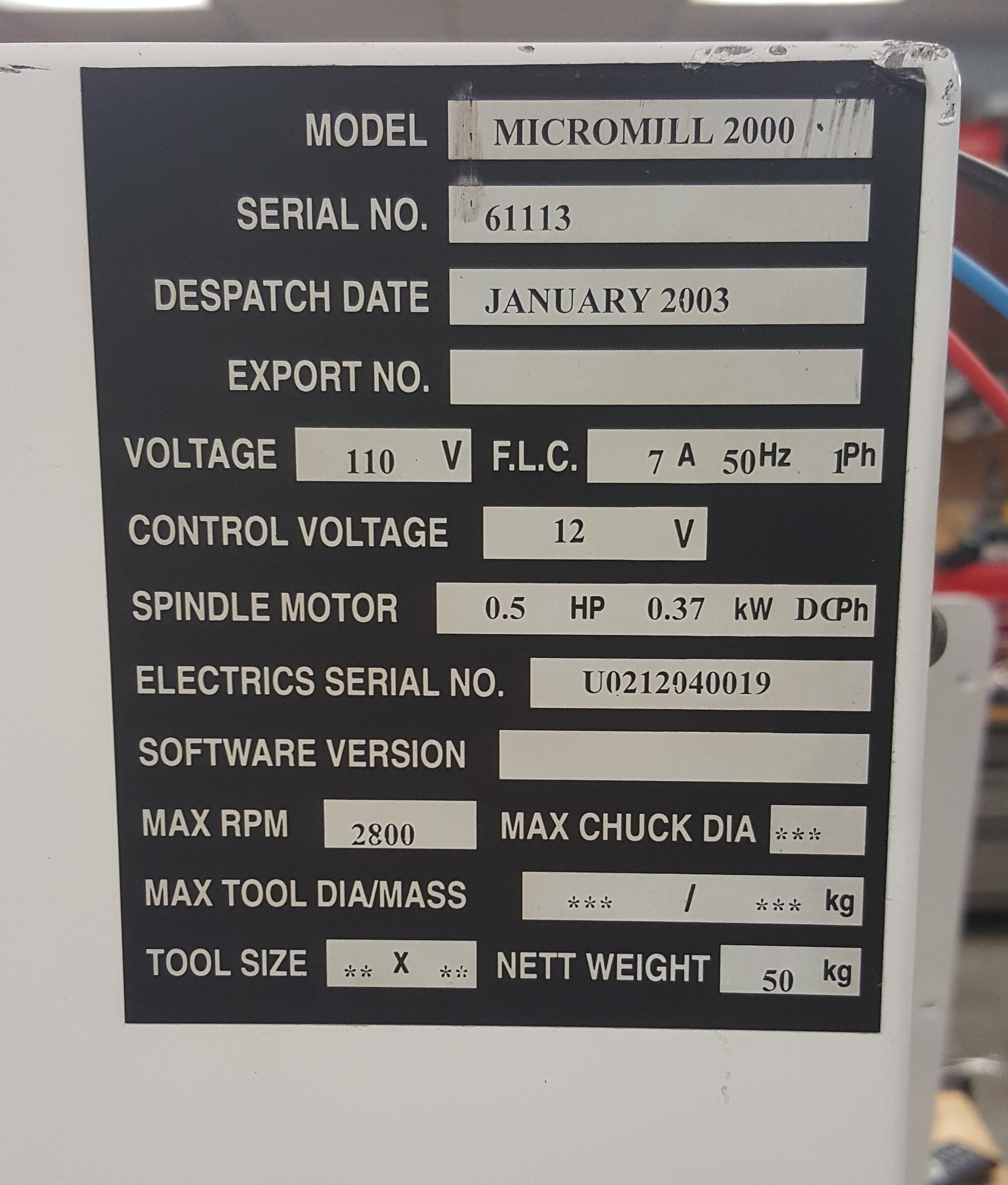
Cliff Burger is part of a makerspace ( http://www.tcmakerspace.com ) which had a Denford Micromill 2000 (January 2003 dispatch date) donated to them. When referring to my four part series( 1, 2, 3, 4) about how I got mine working under CNC control, they noticed a few differences with their model and wanted to share that information.
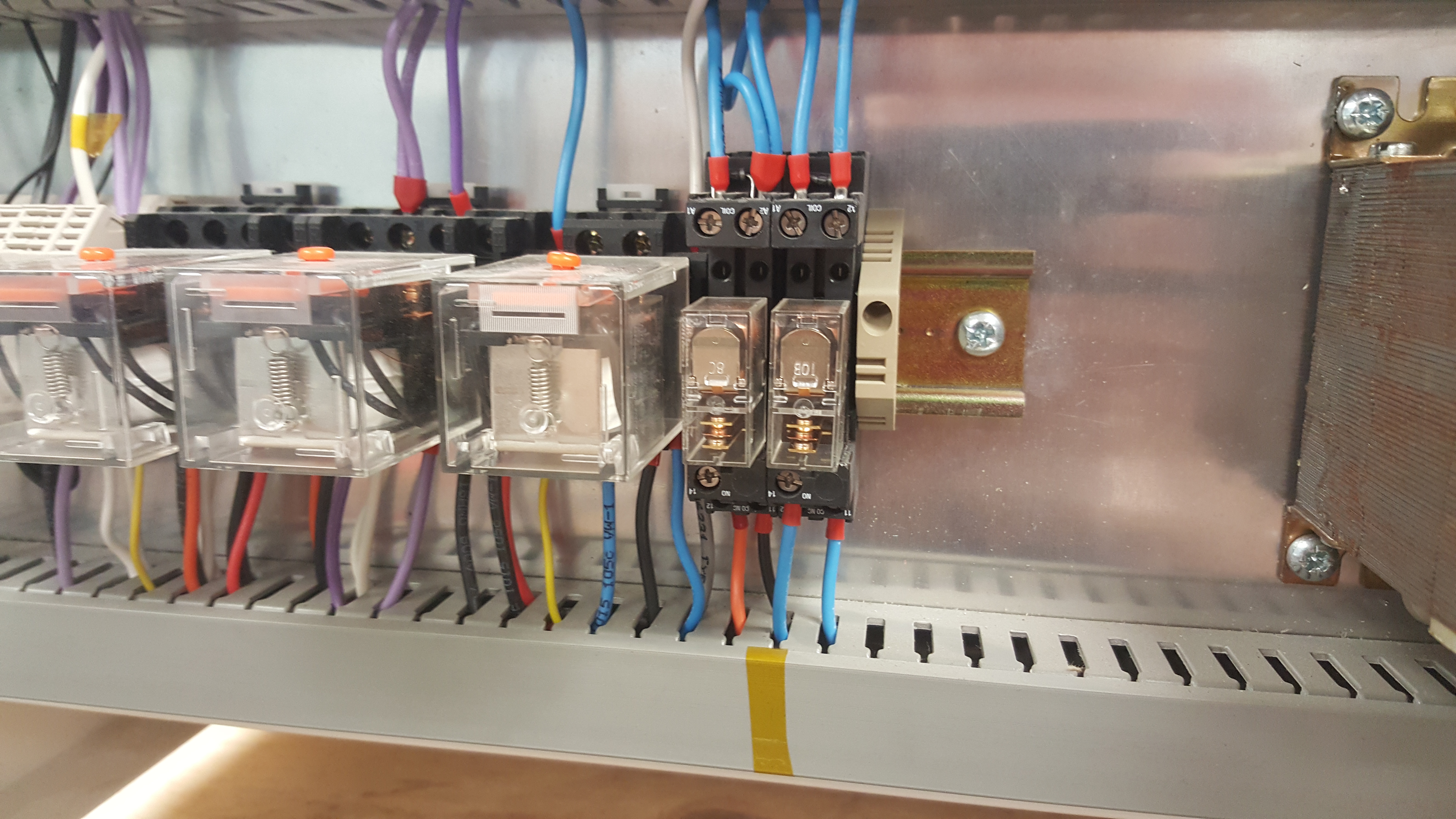
Instead of having a custom made relay & power board, their mill has it’s relays mounted to a DIN rail (bottom left of the case in the image below). The spindle go relay (SGR) is located in the 2nd from the right position.

A quote from Cliff:
On the DIN rail, the spindle activation relay is the second one in from the right. It’s a 12v relay with the ground for the coil being controlled by the C6 pin. However, currently the relay never sees a 12V signal either. Not sure if it’s something wrong with my board or it’s waiting for another command signal before it sends the 12V out as well. Either way, I’ll likely just get a 5V relay and switch it right off the BOB, but for the time being I’ve moved the orange wire from the “14” position to the “12” position to supply power to the board at all times.
Cliff also sent along his mach3 config file, which you can download here (note, you will have to remove the .txt extension from the file to use it.) Denford.xml.txt
He has the following caveats:
Things to note about the mach3 config:1) My limit switch are on different pin numbers due to me chopping 1 wire a bit shorter than I should have (oops!).2) default units are in inches so the steps per INCH are correct, but may need slight tweaking for each application.3) backlash settings will need to be measured for each mill, or disabled.4) I’m running a UC100 UBS adapter board so Mach3 may give an error message the first time you open it with this config file.

 interior photos")


Pingback: How to convert a Denford / ScanTek 2000 Micromill to LinuxCNC / Mach3 control: Part 3 — Spindle Motor Control | Jay's Technical Talk
Hi Jay,
I have yet another version of this mill… a Sherline setup but with a different controller board and relay setup. Mine is labeled Optimised Control Limited, Bristol, England, D771 Issue 3, and the original CPU board is serial only. The pinout for the three rows of 32 pins is the same, but I had to tie the parallel port breakout board’s output pins to high for Mach 3 to read the home switches.
I’ve documented some of it here: https://talk.dallasmakerspace.org/t/craigslist-find/30307
Feel free to reuse any pics if you wish to update your blog.
Raymond
Glad to hear you got it working! Definitely an older control board.
After digging this thing back out I believe I remember why I parked it. I have yet another version with the SGR also DIN mounted. It appears the spindle only has speed control via the potentiometer. There are no wires coming from the Baldor Sout/GND. With my limited understanding in circuits my question is, could I add your spindle control modification along with the two wires that I’m missing from the Baldour Sout/GND to the spindle control board, and then just manually switch the spindle control on from the front panel before running gcode?
Here are some pics:
https://photos.app.goo.gl/Es2RQVM2SjadDz1Y9
Thank you
From your photos, it appears your Baldor board is the same as mine and contains the 0-10v spindle control circuit. (no guarantee it is used…..)
Check out the white/blue/red wires from P1/p2/p3. If P1 and P2 go to the end of the baldor (NextMoveST) board you are golden.
(one is ground, one is the input control voltage, and the third is +10v)
If they ONLY go to the pot on the front panel, my approach may not work…but you MIGHT be able to re-route the P1/P2 cables to the baldor board, connect in where I did and use the Baldor board to produce the 0-10v input signal.
Definitely read this post as well if you haven’t already:
https://www.summet.com/blog/2016/01/29/how-to-convert-a-denford-scantek-2000-micromill-to-linuxcnc-mach3-control-part-4-spindle-speed-control/
Thanks Jay,
P1 and P2 run straight to the pot. What you’ve mentioned about re-routing them to the Baldor is what I’m hoping will work. I’ll definitely be referencing your part 4 write up for speed control. I’m just hoping I can get by without part 3 (where you energize the SGR using the transistor/BOB circuit), instead I’ll be switching the SGR manually with the power switch on the front panel and then attempting to control the spindle speed from the 0-10v input. I don’t know if this is going to cause any issues down the road.
On my system P1 goes to “Spindle Ground” and P2 goes to “Spindle Analog” on the TB7 connector (bottom left connector of the Baldor board). Spindle Analog is the pin on the far left, while Spindle Ground is the #2 pin counting from the left.
Speed control should be completely isolated from the “on/off” control, so you should be able to set up only the speed control. Good luck! (Worst case scenario, you’ll just have to buy a BOB that includes a 0-10v analog output.)