Overview and results video:
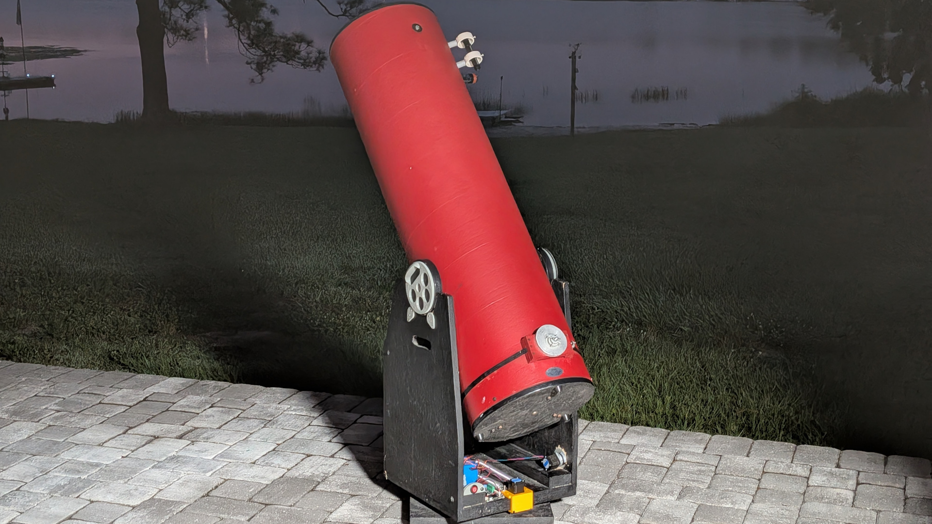
I have upgraded a used Odyssey 1 Dobsonian telescope (Rockerbox design with teflon bearings that the user would manually push around for visual observation) to be automated using stepper motors controlled by the OnStepX software running on a Fysetc E4 controller board.
If you want to follow along with the whole procedure, I’ve documented most of it in a series of videos on YouTube.
Software
Flashing the Firmware on the Fysetc E4 board ( http://wiki.fysetc.com/docs/E4 )
OnStep Wiki: https://onstep.groups.io/g/main/wiki/32747
OnStepX Wiki: https://onstep.groups.io/g/main/wiki/32794
Using the smart web server plugin for configuration and stepper motor testing:
Mechanical:
Replacing the original rockerbox 3 Teflon supports riding on a piece of laminate with a Lazy Susan bearing.
The “lowest effort” Az motor holder (L-bracket, strap hinge, 2×4 & spring).
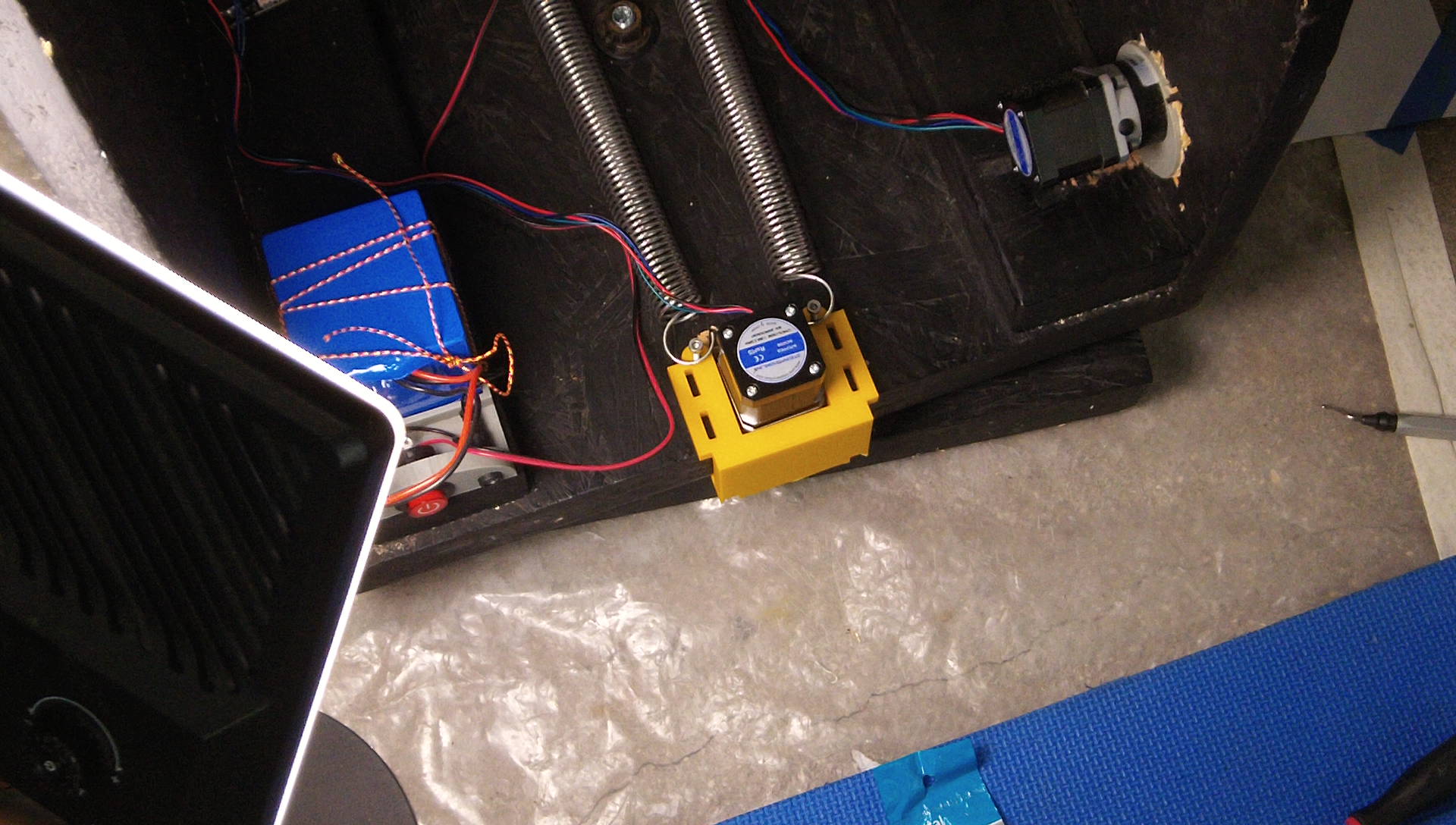
I’m using a 10:1 Planetary Gearbox stepper motor with a pulley and o-ring as a wheel to drive directly against the outside edge of the Lazy Susan bearing.
(This mount actually works just fine, but I eventually replaced it with a 3D printed one that takes up less space and looks slicker.)
A 3D printed motor mount for the Azimuth axis that uses spring tension.
https://www.printables.com/model/1879682
I have been very happy with the AZ axis drive system. The super simple direct drive wheel on the Lazy-Susan bearing has about 21 arc-seconds of backlash (much better than the belt drive system for the ALT axis, which is measured in arc-minutes).
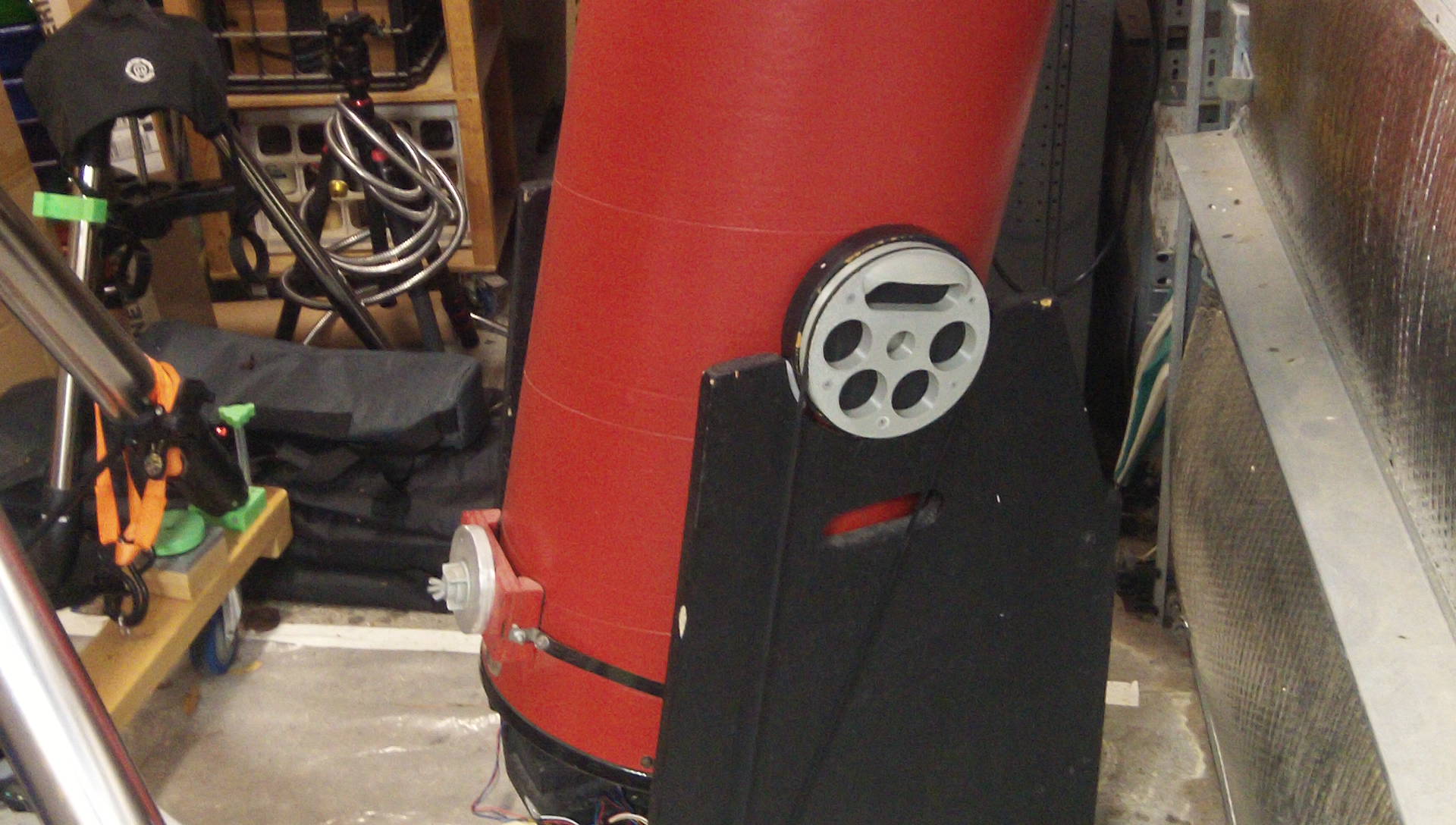
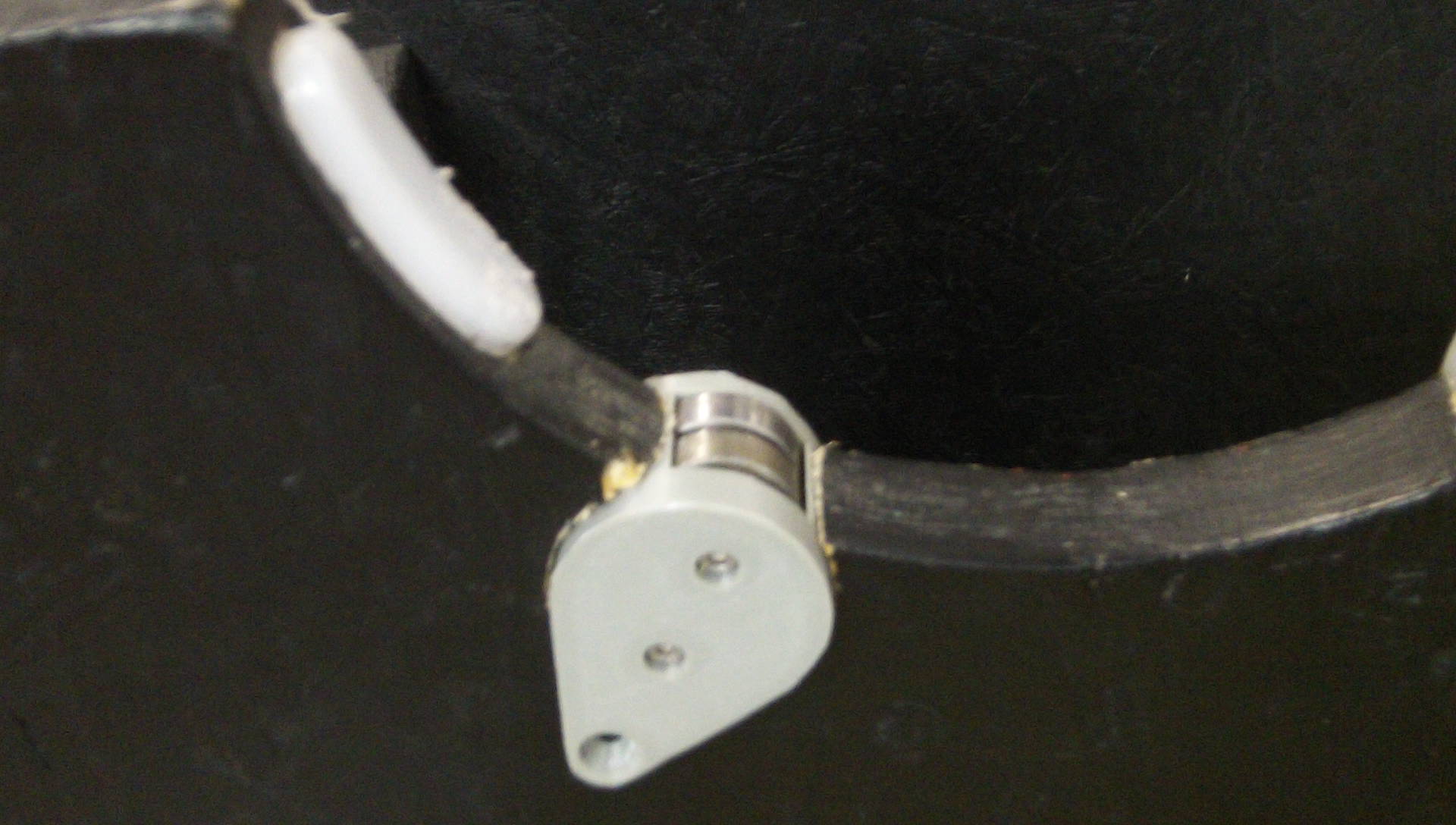
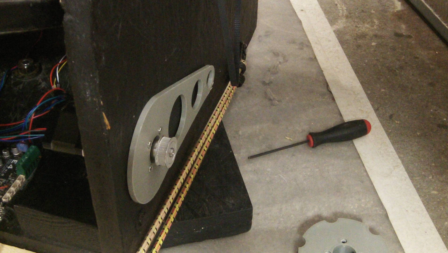
For the Altitude axis, I designed a 3D printed gear (that includes a handle) that screws onto the optical tube assembly with 240 teeth (GT2 timing belt, 6mm wide) and am using a 40 tooth 8mm bore pulley on a 100:1 Planetary gearbox stepper motor held in a 3D printed “cam action” tension adjusting motor mount.
ALT OTA Pulley w/ Handle 3D model & STL file: https://www.printables.com/model/1879682
I’m proud of the cam action belt tension adjustment motor mount that I designed, as it is a clean and elegant solution to mounting the stepper motor pulley and also being able to adjust the tension on the belt drive. You can see the 1 minute short into here:
https://youtube.com/shorts/Mmhttps://youtube.com/shorts/MmHQwkkMlJ8HQwkkMlJ8
ALT Motor Mount & Belt Tensioning system 3D Models & STL file: https://www.printables.com/model/1879723
The Alt axis was very “jerky” as the pulley belt drive system was fighting friction of the traditional Dobsonian bearing system, so I added 3D printed roller bearings to make the OTA much easier to rotate.
Roller Bearings 3D Model & STL Files: https://www.printables.com/model/1879797
I added limit switches to my ALT axis so that if the OnStepX controller gets confused about where it is the stepper motor won’t drive the OTA into the rockerbox (by going below -4 degrees or above 90 degrees). The default E4 board firmware from the web flasher has all emergency stop / limit switches tied to the X-min plug, so I bought a JST HX 2.54mm (0.1in) 2pin plug and soldered two switches to it in parallel. I found a place to mount them orthogonality in a single 3D printed mounting block such that one switch its triggered at each end of the OTA’s range. Unfortunately, I can’t use them as Y-axis homing switches without editing the config.h file for the firmware and compiling it myself, but they do protect my ALT axis. [The OnStepX software does a good job of respecting software limits, but as my OTA is removed and re-installed every time I set up the telescope, having hardware limit switches is a good backup.] My AZ axis can rotate 360 degrees without any cord wrap (as I’m using a battery within the rockerbox to power the system) so I don’t need a limit switch for it.
Limit switch mounting block model & STL files: https://www.printables.com/model/1878136
Software Calibration
You then have to calibrate the software with the correct steps per degrees, which is relatively easy if you are using a set of pulleys with a known tooth count ratio (240 : 40) but if you are using a random lazy-susan bearing and a wheel you made yourself with a pulley and an o-ring you may need to experimentally determine how many steps it takes to make a full revolution of your telescope.
The results (the ability to GOTO using my SkySafari 8 app and tracking to keep objects in the eyepiece for multiple minutes (visual observation only, not trying to do any astrophotogrpahy) are all that I had hoped for.
I also calculated the backlash in each of my axis ( 21 arc-seconds for the AZ axis, and 18 arc-MINUTES for the long belt driven ALT axis). Configuring the backlash in the OnStepX software isn’t strictly necessary for guiding, but can make GOTO and manual skewing a bit more accurate.
Bill of Materials (parts used & costs):
- 16″ (400mm) Lazy Susan bearing for Az axis $35
- 8x 608zz bearings (Alt Rollers) $8
- FYSETC E4 Controller Board (No-Wifi [antenna] = internal Wifi variant) $ 31.80
- Stepper Motor plugs for FYSETC E4 board: JST XH2.54 4-pin 5 pack [Ebay: dream-shop7] $10.25
- Limit Switch plugs for FYSETC E4 board: JST XH2.54 2-pin 20-pack $6.99
- 10:1 Planetary Gearbox Nema 17 Stepper Motor for Az Axis 17HS15-1584S-MG10 $27.50
- 100:1 Planetary Gearbox Nema 17 Stepper Motor for Alt Axis 17HS15-1584S-MG100 $33.65
- 31mm OD V-Groove pulley with 8mm bore (Az Axis wheel) $10
- o-ring AZ Axis “tire” (21mm ID, 31mm OD, 5mm thick, Buna-70) [Ebay:swint101] $10.31
- (Note: Instead of using a V-Groove pulley and O-Ring for tire, you can purchase a Knurled Polyurethane Roller that is designed for the job, but it may take a month to arrive from China, or be very expensive if you purchase it from McMaster. 8mm (bore) 30mm OD, 18mm (total height). I bought this one, but haven’t tested it yet: https://www.ebay.com/itm/389642609342?var=656943903999 )
- 2pcs Extension springs (0.08″ x 1″ x 7″ 304 stainless) (for tension on the AZ axis) $16.99
- 40 tooth 8mm bore GT2 timing belt pulley (6mm width) Alt Motor $12.98
- GT2 6mm wide timing belt. Your length may vary 1350mm is a common one and easy to find, I used 1524mm belts because that was what fit my telescope box best. $14.89
- 12 volt 15Ah LiIon battery to power the system and prevent cord-wrap. (Note that you could probably get away with a 5 or 10 Ah instead of this 15 Ah battery depending upon how long you intend to use your telescope. Or you could substitute a much cheaper 12v power supply and an extension cord.) 45.99
- Power switch (or substitute with any switch you have on hand) $6.89
Total cost (not including many random screws I used which I already had on hand): $253.24
This isn’t an unreasonable cost to automate a telescope, but it doesn’t include the time investment, so I definitely recommend you buy an off the shelf kit if one is available. In my case, I had paid $200 for the used telescope, so I’ve more than doubled it’s cost.
As these experimental projects go, I purchased many things that I didn’t end up using, [I have a large collection of GT2 pulleys and belts, o-rings of various sizes, 5mm bore hardware I ended up not using with a non-gearbox NEMA 17 stepper, etc….] but if you are buying the stepper online steppers I recommend above, I also suggest you buy a matching set of brackets in the same order to combine shipping, even if you are planning on using 3D printed brackets, it’s nice to have the metal L-brackets on-hand that match your motors.
- Nema 17 Bracket for High Precision Planetary Geared Motor Alloy Steel Bracket ST-M8 $2.29
Tools that are going to significantly add to your costs if you don’t already have them:
- 3D printer ($500-$1000) for the large 240 tooth gears sized for your OTA, and misc motor mounts, battery mount, etc… Depending upon your telescope model, you may be able to find somebody selling a pre-printed gear designed specifically for it.
- Drill & bits (cutting holes, driving screws, etc)
- Hole Saws to cut the holes for mounting the roller bearings and Alt motor mount cam action system, I used 1.5″ (roller bearings) and 2.5″ hole saws (ALT stepper mount).
- Saws (hand or powered) [To cut a slot for the Az motor mount]