
I had to repair the cable on one of those “500 in one classic game consoles” that look like a mini Nintendo Entertainment System (NES) but don’t actually say the “Nintendo” trademark on them anywhere.
An example can be found on Amazon here:
https://amzn.to/2JBgzSS
The order of the wires inside the controller on the PCB (NES01-JOYV1.1) is (from left to right): orange(red), yellow, blue, brown, white
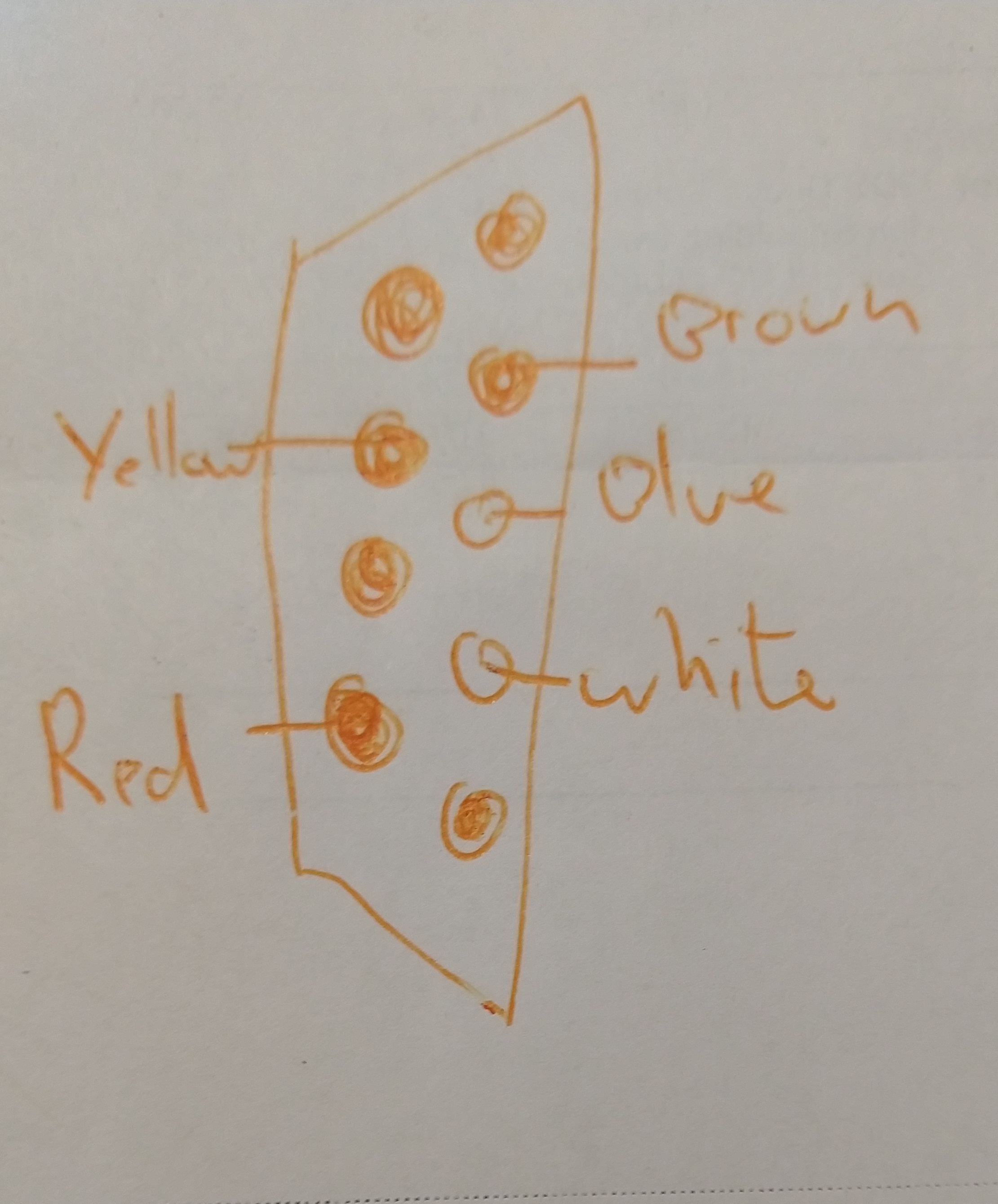
The pinout for the wire colors at the end of the cable is as follows:


How did you get into the plastic end that plugs into the system? I have one of these controllers that isn’t working and the 5 wires appear to still have a good connection to the “motherboard”, but I’m thinking one of the wires either is broken or not connected inside the plastic piece that connects to the system.
Thanks!
I never opened up the plug/connector end, just put a needle inside to detect which wire went to which plug. The easy solution is to buy a set of replacement controllers, they are not that expensive online.
Not sure if anyone is still following this post but I have this same pcb/controller(NES01-JOYV1.1) and I was wondering how many volts the pcb for the controllers themselves pull. I can’t see them taking more then 3.3v each but I could be wrong. Also knowing which wire colors are ground and live would be incredibly helpful. Thanks in advance.
I’m afraid I was repairing the controller for a friend and never had access to the game console itself so I couldn’t measure the voltage or polarity. If you are trying to get one of the controllers working stand alone, start at 3.3v and then move up to 5v if nothing works. (many “5v” chips will actually work at 3.3v nowadays and are 5v tolerant).
If I had to guess, I’d say red(orange) was + and brown was GND, but that is only a WAG based upon wire color and the fact that they are on opposite sides of the plug…
does anyone has an idea on how to put this wires to normal usb? i have one of this controllers and want to use the motherboard to make an usb gamepad
Did you make it happen?
late as hell to this but i picked one up at thrift store, making it into a retropi, did you succeed in turnig usb? if so, how. lol
https://wiki.nesdev.com/w/index.php/Controller_port_pinout
This document is pinout list.
TB, TA is speed X2.
https://www.allaboutcircuits.com/projects/nes-controller-interface-with-an-arduino-uno/
this code using, Right button is Jump.
https://www.nesfiles.com/Forums/Hardware/0/455
Those documents appear to apply to the original NES controller, not this “replica” mini-game unit.
I want to use the motherboard from a mini classic and take the wire with jack attached from a mini retro and hook it to the motherboard but classic is (r+y+bl++br+w )retro(Gr+bl+w+y+red org) does r+y+w go to the other+y+w (ETC)how does that go???
I’m sorry, I gave this back after fixing it, so I don’t have it available to look inside. The photos and descriptions here are all I have.