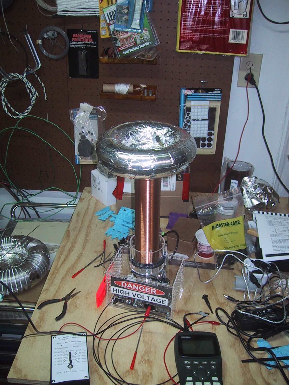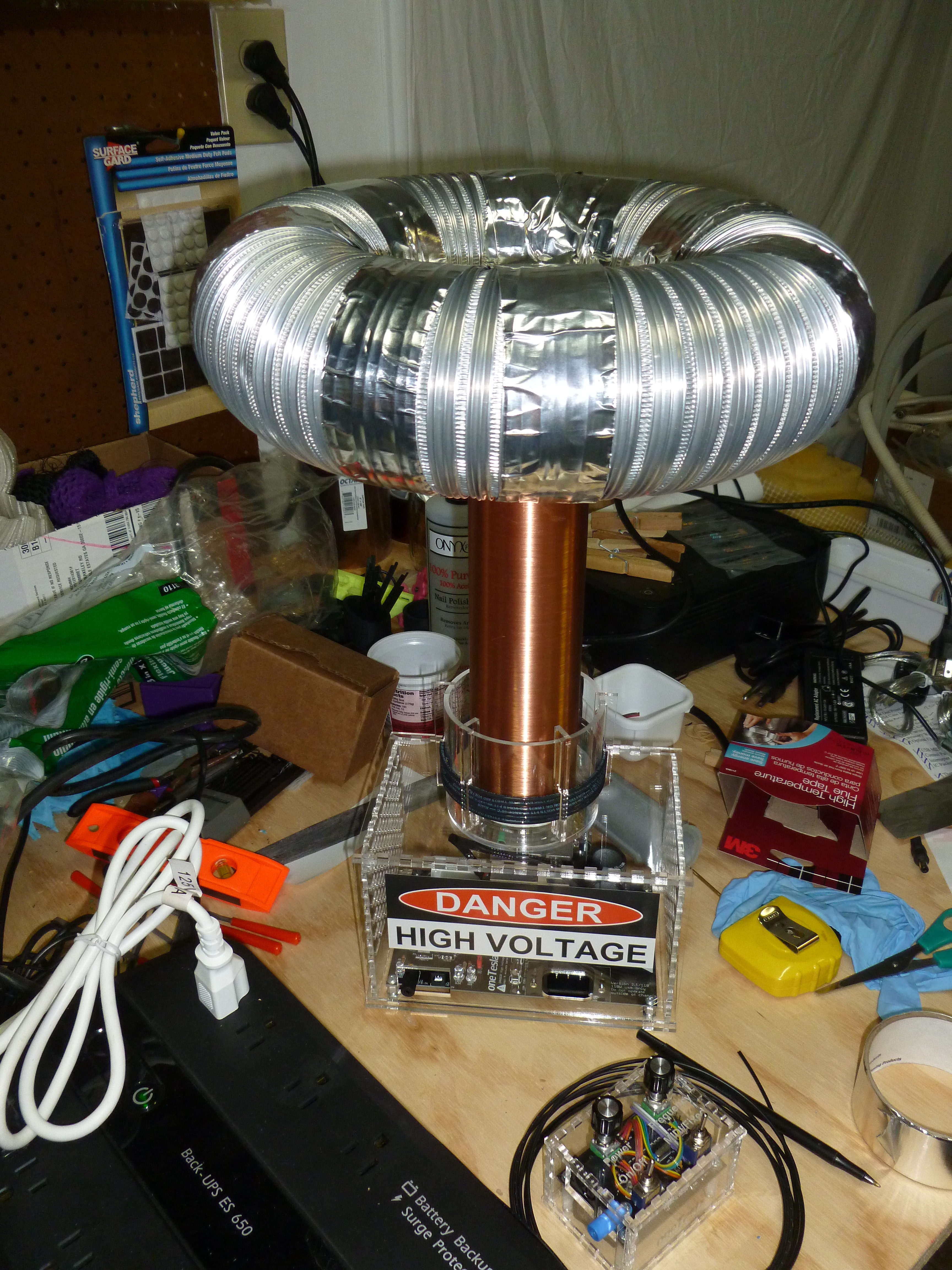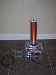
Big Picture:
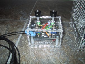
I was one of the first 100 backers of the oneTelsa Kickstarter (120 volt) and received one of their earlier kits (manual revision 1.3.0). Overall I was very happy with the kit. The overall build quality of the resulting Tesla coil (and especially the case) is much nicer than I could have achieved on my own without a kit, and the laser cut acrylic parts fit together very closely.

Because this is the first product the oneTesla team has shipped, and they are just starting out, some mistakes are expected. My kit did have one major problem: They accidentally shipped a 220 volt circuit board (for Europe or other countries that don’t use the 120 volt standard) and omitted the interrupter board entirely. Everything else in my bag of parts was set up for 120 volts. After a quick email to the oneTesla team they shipped me the correct circuit boards and I was able to solder them up. There were a few other minor hiccups with the kit (a missing screw, an extra fourth wire in the gate drive transformer pre-twisted wire set, weird reversed green LED’s, and a missing 2 pin jumper header that I replaced from my stock) but nothing else that was a real show stopper. The 1.3.0 manual was missing a few minor assembly steps, but nothing you couldn’t figure out from looking at the pictures and the parts lists, and most of those have been fixed in the 1.3.3 manual online.
Issues/suggestions for somebody else building a kit to think about:
Reversed Green LED’s
At least in the kit I received, the green LED’s were “backwards” in that the flat edge of the LED should be mounted OPPOSITE the flat edge in the circuit silkscreen. I believe they bought budget surplus gray market LED’s and got stuck with a batch with this weird manufacturing defect that a large company had rejected. This is documented in the errata online, and I didn’t make the mistake on the main board, but for some reason I didn’t remember to double check what color the LED was for the interrupter board. [Everything works with the LED reversed except you don’t get the power indication light ….but I decided it was worth fixing so that I didn’t accidentally run my battery down because I forgot to turn the interrupter off.]
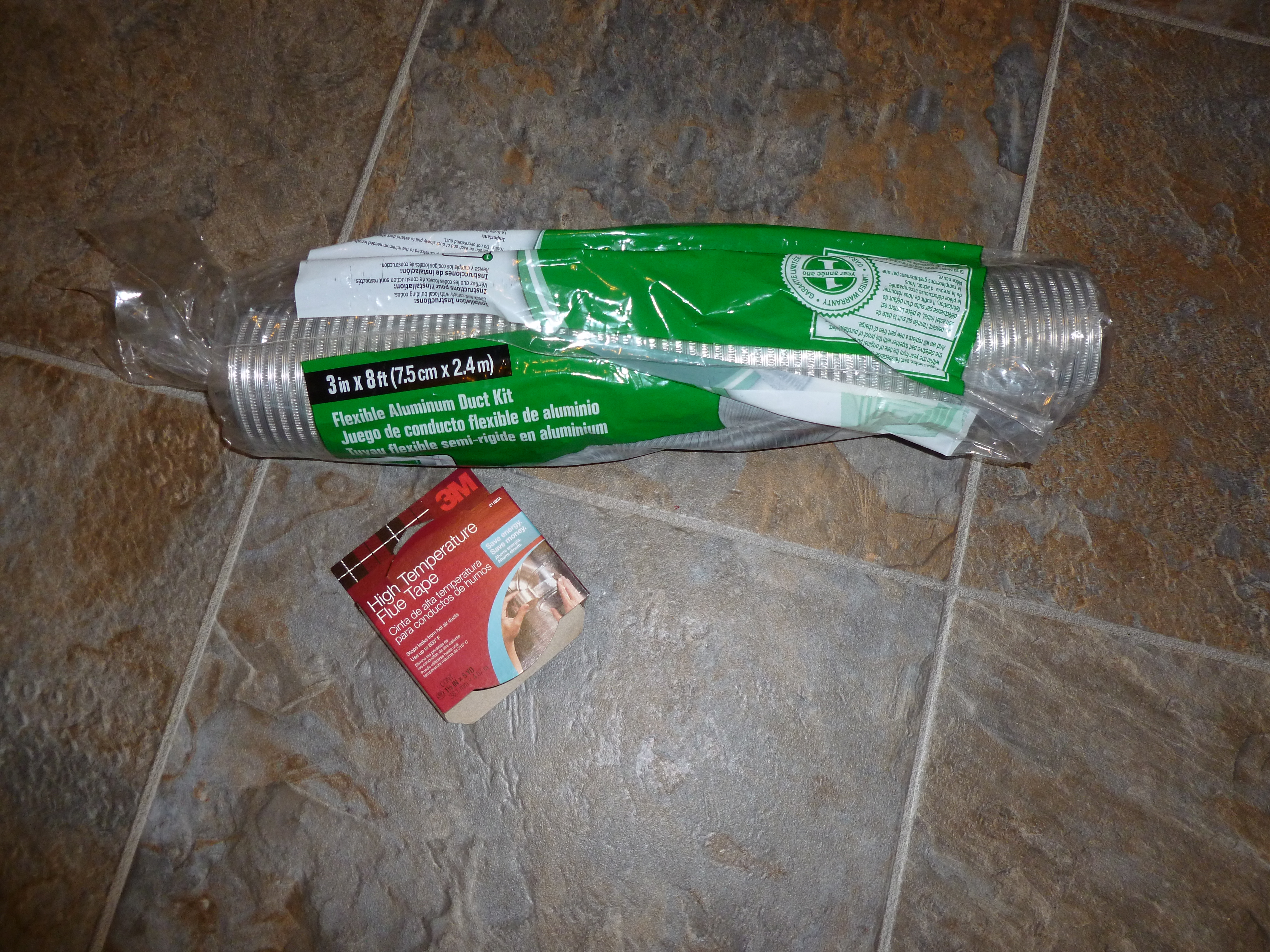
Alternate Glue
They recommend using hot glue to affix all of the acrylic pieces. This would work, is somewhat reversible, and many people will already have a hot glue gun or can easily buy one locally. However, for the best visual appearance, I would recommend using acrylic welding solvent instead. Of course, acrylic welding solvent is scary stuff, so if you use it, read the warnings and wear nitrile gloves!
I used IPS Weld On 3 (McMaster Carr part number 7528A13) for both cases and the primary core base/clips. It will probably cost you as much as a hot glue gun to buy, but a one pint bottle will weld a LOT of acrylic. First, make sure you have the case assembled correctly, with all of the holes/slots lining up with the circuit board. Remember to try reversing the bottom piece if things are not lining up. Pay special attention to the slot where the wires from the primary core go into the screw terminals on the back. The cases are very nicely designed, but I wouldn’t have minded a few matching numbers etched in the corners to make it very easy to determine the exact orientation of each piece relative to one another.
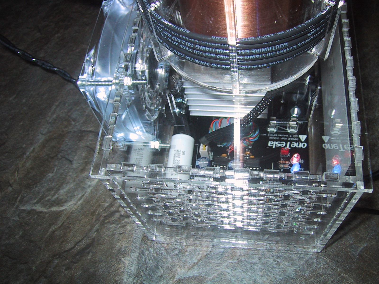
After you are sure you have the cases assembled correctly (I held them together with rubber bands while testing), make sure that you can get your circuit boards into them from the top (they are a very tight fit, my case walls have to bend just slightly when inserting the main circuit board at an angle with a rolling motion).
To glue, lay the case down on it’s side with the base hanging off the edge of the table. (The base keeps the side pieces square.) Then use a q-tip to place a small drop of weld-on on the top of each tab that sticks up through the horizontal acrylic piece. You will see the water thin solvent wicking between the tabs and coating the bases of the joints between the tabs. I did one side (two sets of tabs) at a time with a ten minute wait between sides. Finally I turned the case upside down and affixed the base. Don’t glue on the tops!
For the primary core clips, I used clothespins to hold all six clips on. Make sure they are all straight and their spacing is evenly distributed. I used a coffee stir stick to place a small drop of acrylic welder on the top of the clip where it rests against the outside of the round acrylic primary form. After those set up (20 minutes) I took one clothespin off at a time and placed a drop of solvent on the top of the clip where it met the inside of the primary form, putting the clothespin back on to hold it in place for another 20 minutes. Finally, I turned the form upside down and placed a drop between the “U” bottom of the clip and the top of the form while rotating it slightly in my hand to use gravity to get the solvent to wick between the top of the form and the bottom of the clip’s “U”.
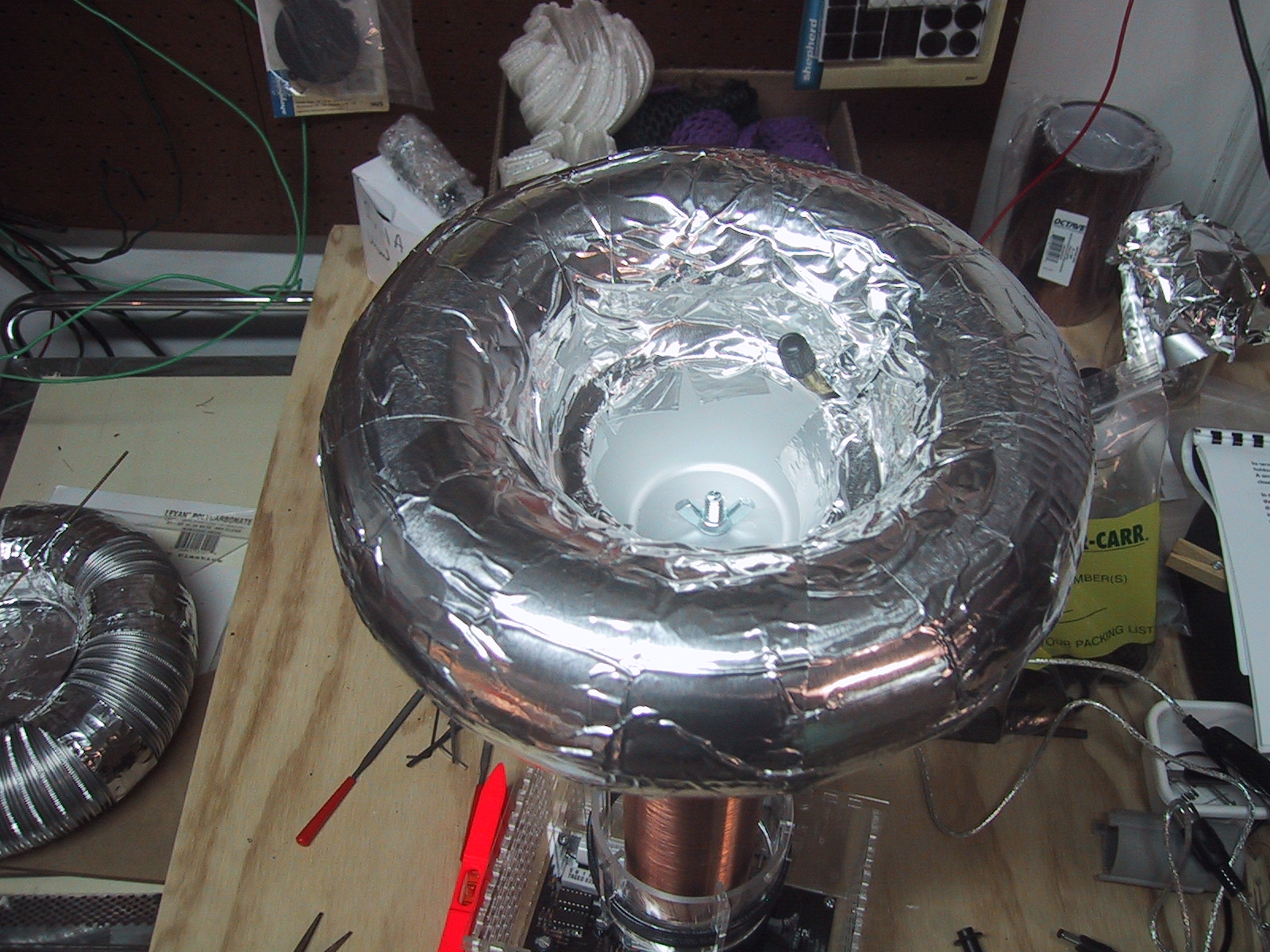
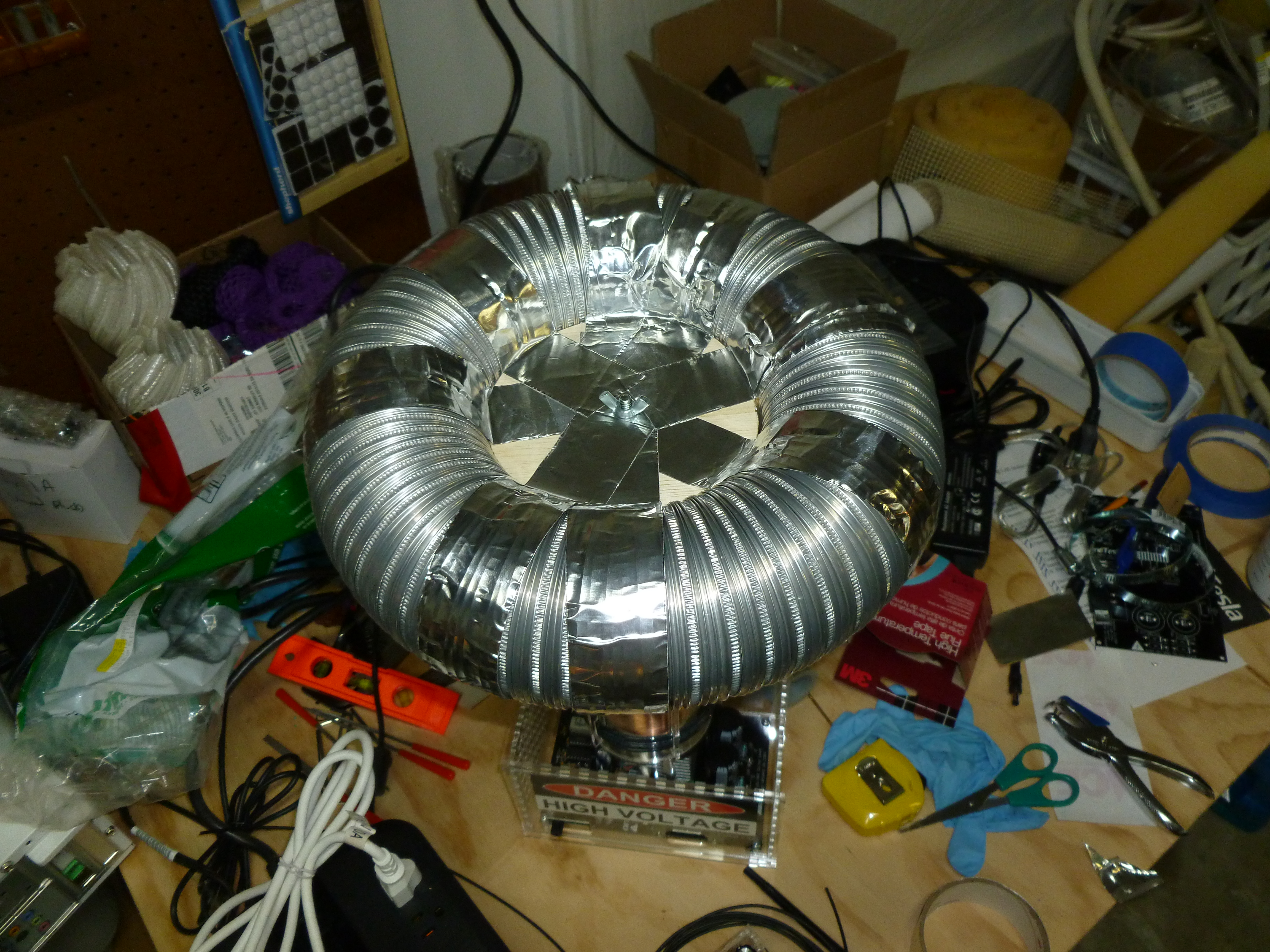
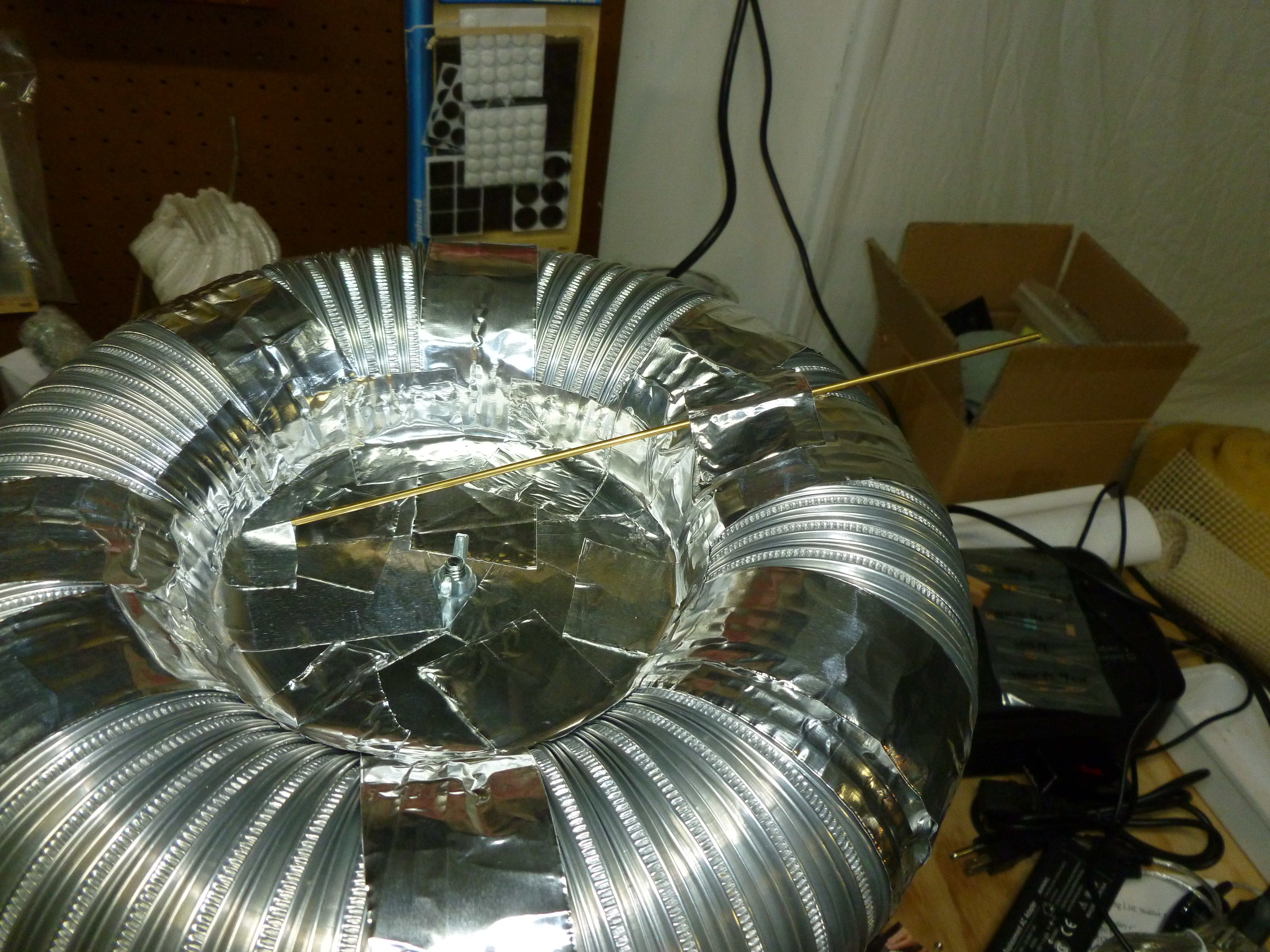
I did use hot glue to affix the top and bottom circles for the secondary core as that was an acrylic to ABS joint, which IPS Weld-On #3 isn’t good for, and it was a hidden joint anyways. I glued the bolt with magnet wire soldered to the terminal ring onto the acrylic circle while holding the bolt head in a pair of pliers, and used the wing nut to pull the bolt in tight. After the bolt was tight, I put extra hot glue all around the bolt head. Be sure to test your resistance between the bolts is less than 300 ohms (I got 228) before gluing the ends onto the secondary PVC pipe!
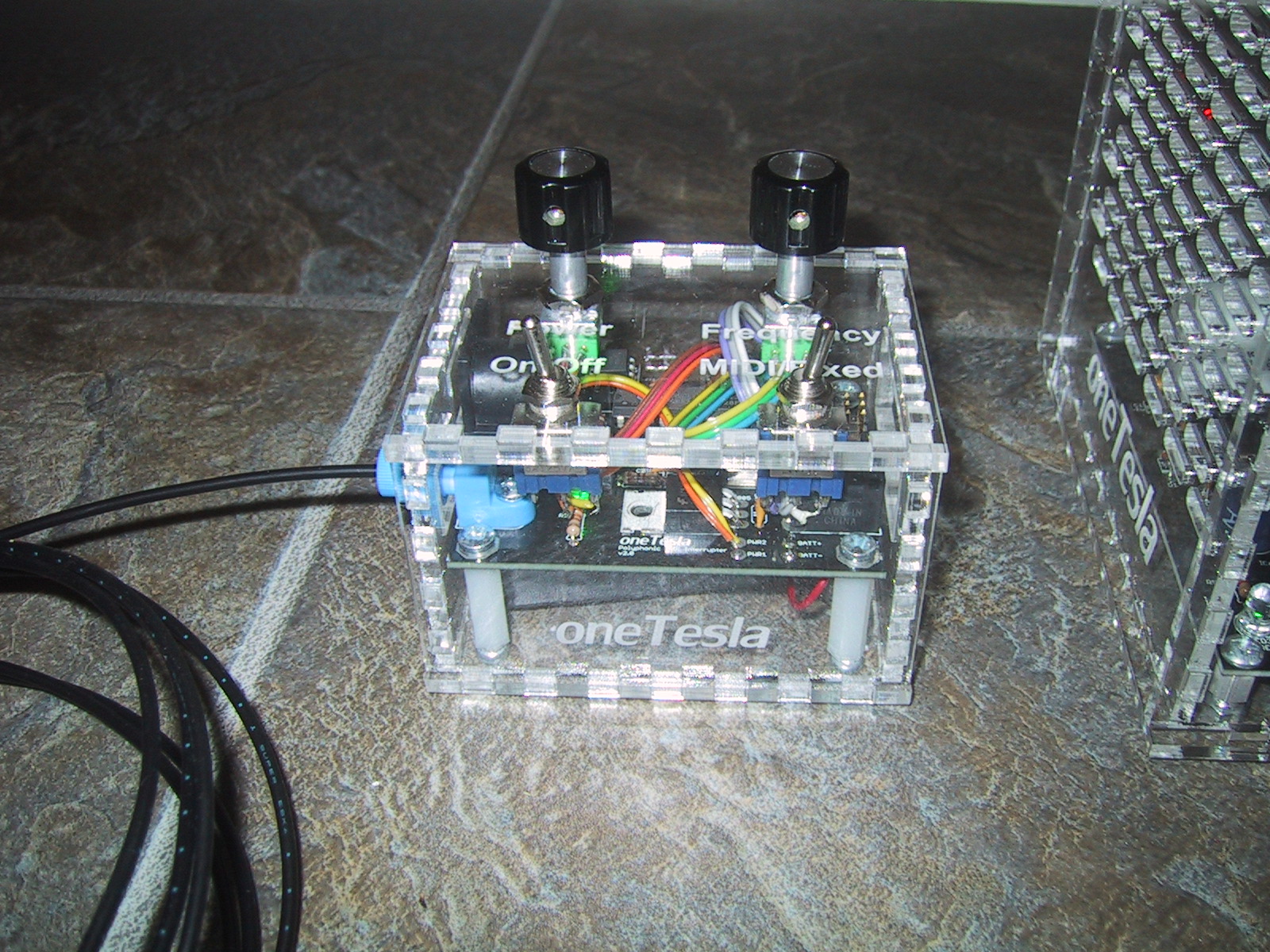
Battery in the interrupter
I was a little worried about the lack of clearance between the metallic case of the 9V battery and the bottom of the leads and solder connections on my interrupter board, so I wrapped the battery in black electrical tape to make sure nothing shorted out.
Terminal substitutions
I substituted a ring terminal for the fork terminal they provided in the kit for the ground wire that affixes to the bottom of the secondary bolt. I feel the ring terminal is less likely to accidentally come off. Their assembly pictures shows a ring terminal on their demonstration model while the manual notes that they provide a fork terminal.
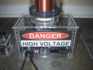
Instead of soldering a wire to the ground terminal on the top of the IEC power inlet, I bent the terminal upright and then used a crimp-on female spade terminal on the end of the ground wire to connect the wire to the IEC ground clip. I don’t plan on removing this connection, but this gives me flexibility for alternate grounding solutions if I need it in the future. For example, I can remove the ground wire entirely and replace it with a ring terminal going to an exterior ground. (It was also easier than taking the circuit board out of my case to solder the wire on, or trying to navigate my soldering iron inside the case.)