Rostock-Mini Tweaks

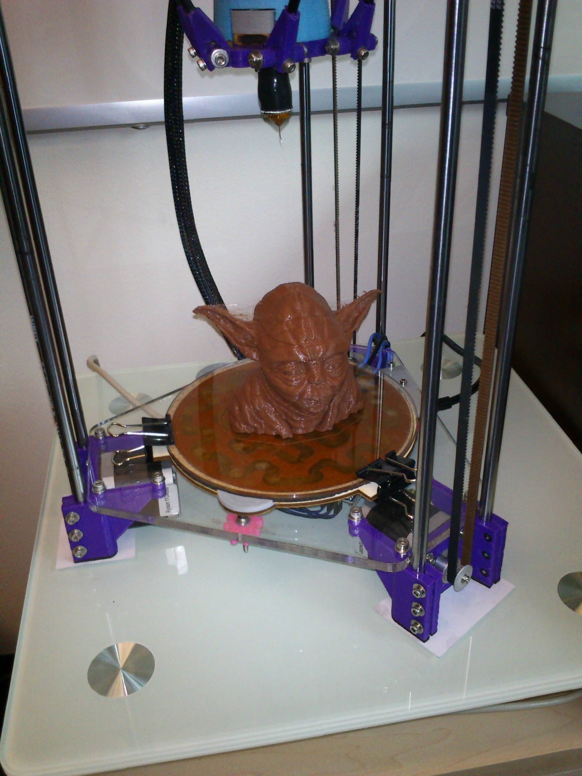
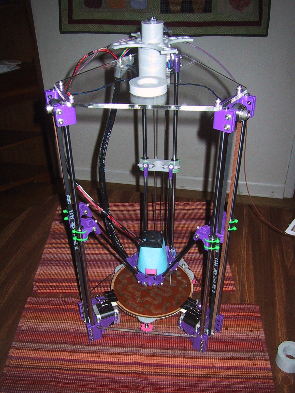
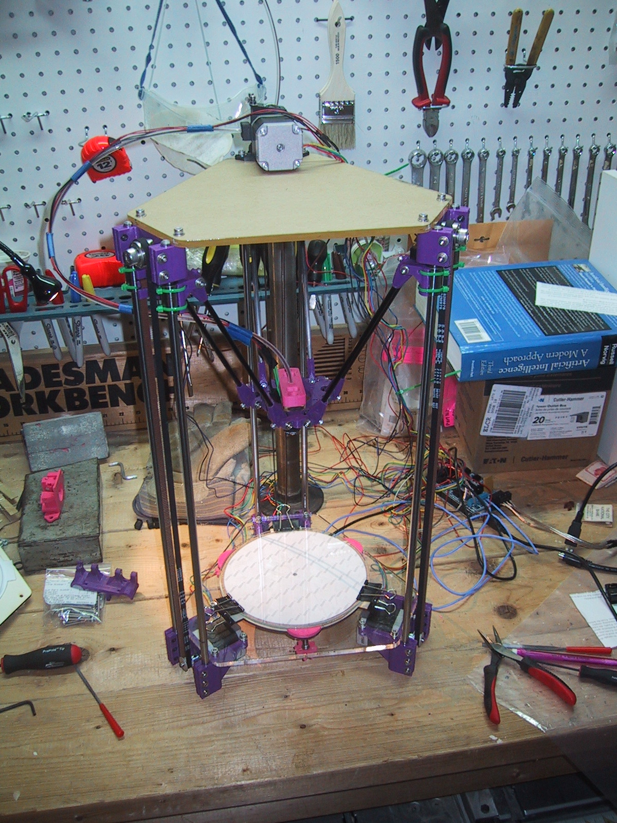
I brought my rostock-mini 3D printer home so that I could take it to a class, and while I had it here, I decided to update a few minor things.

highboy installed

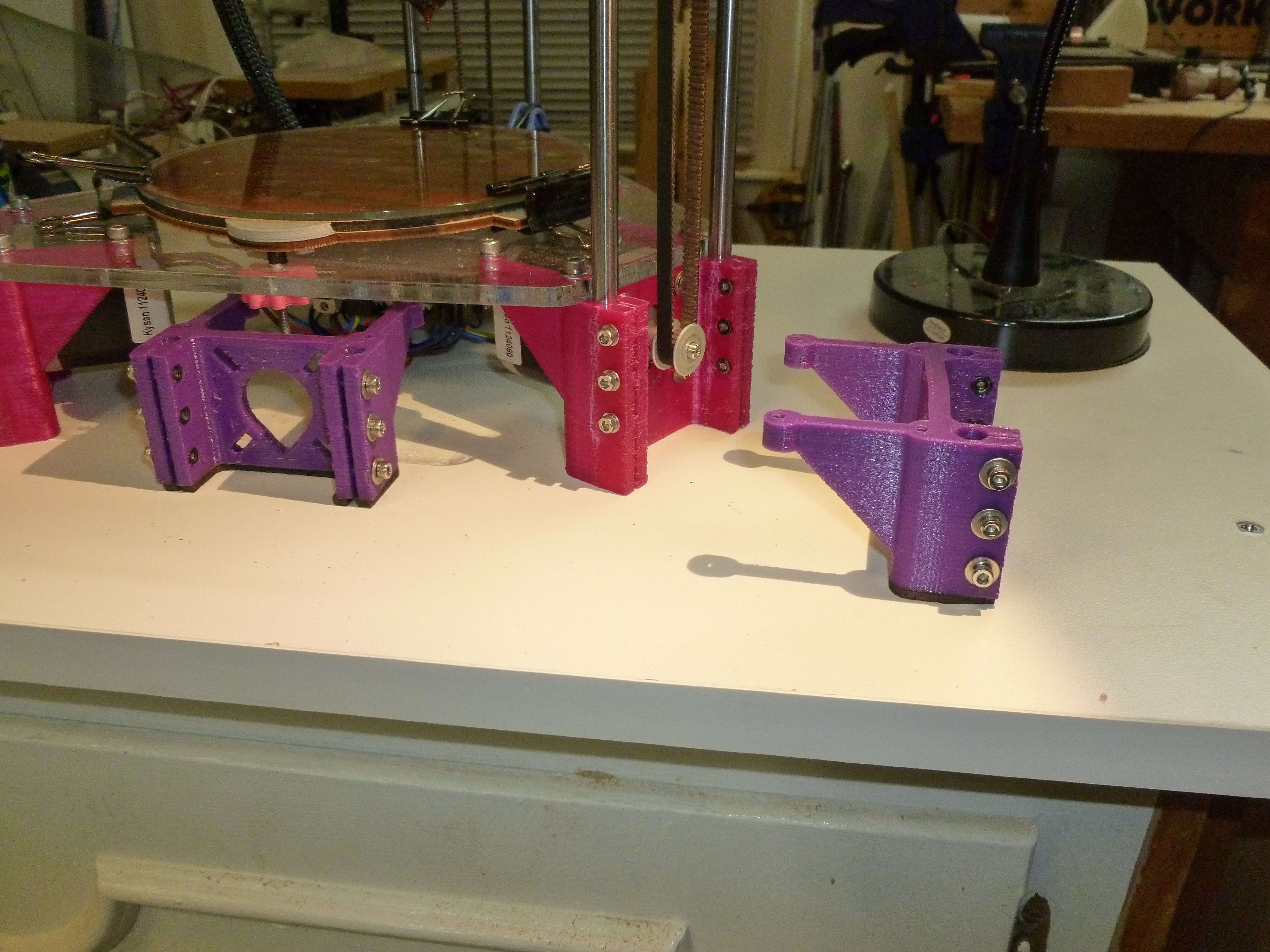
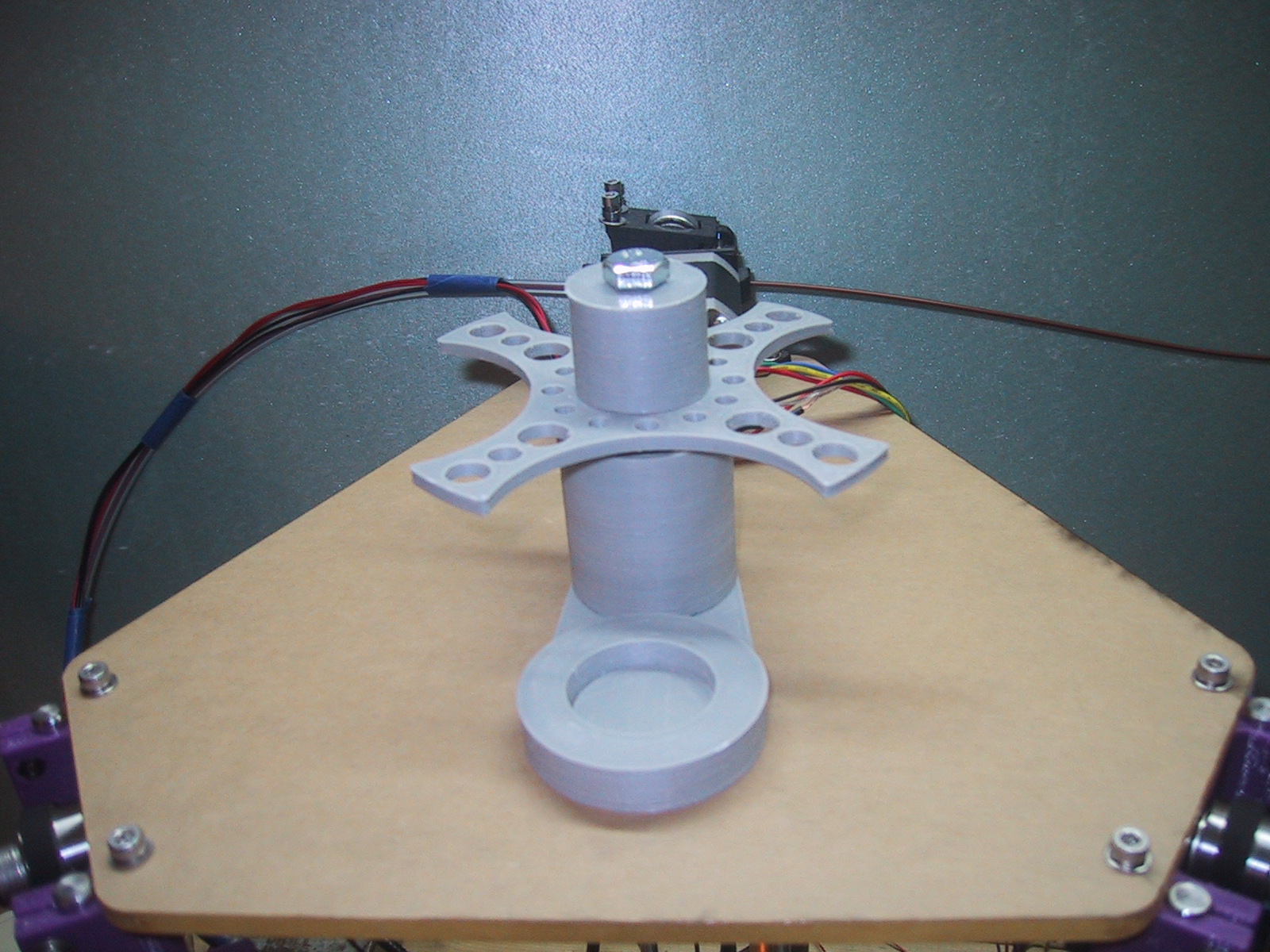
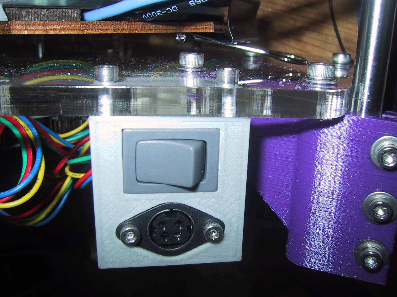
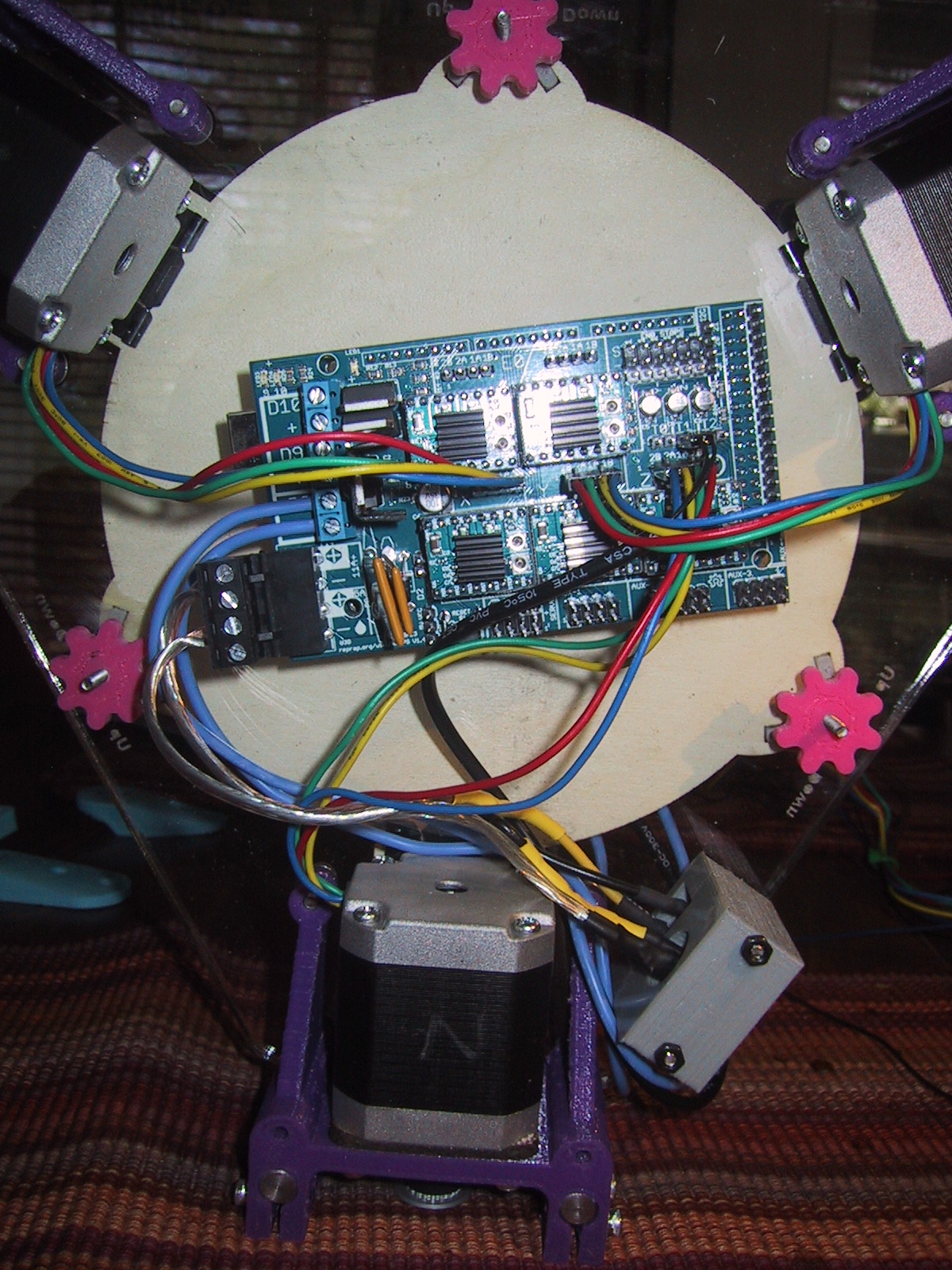
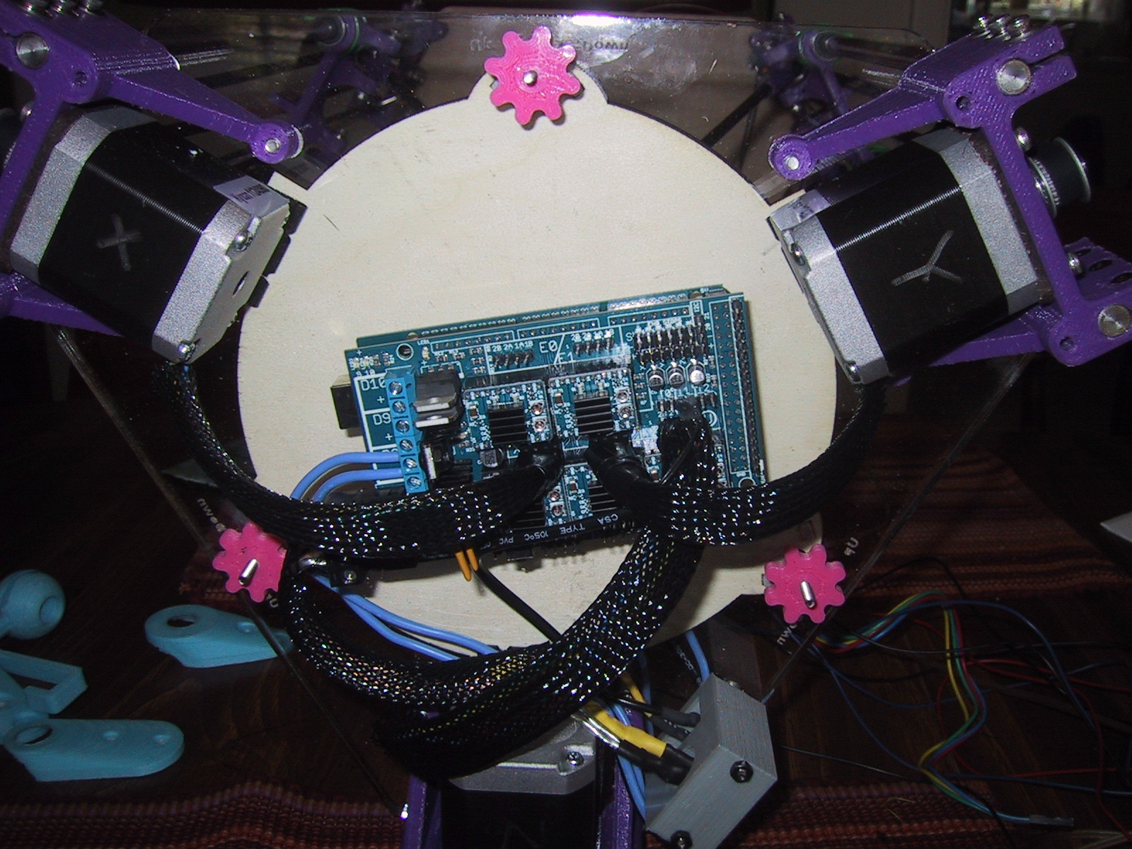
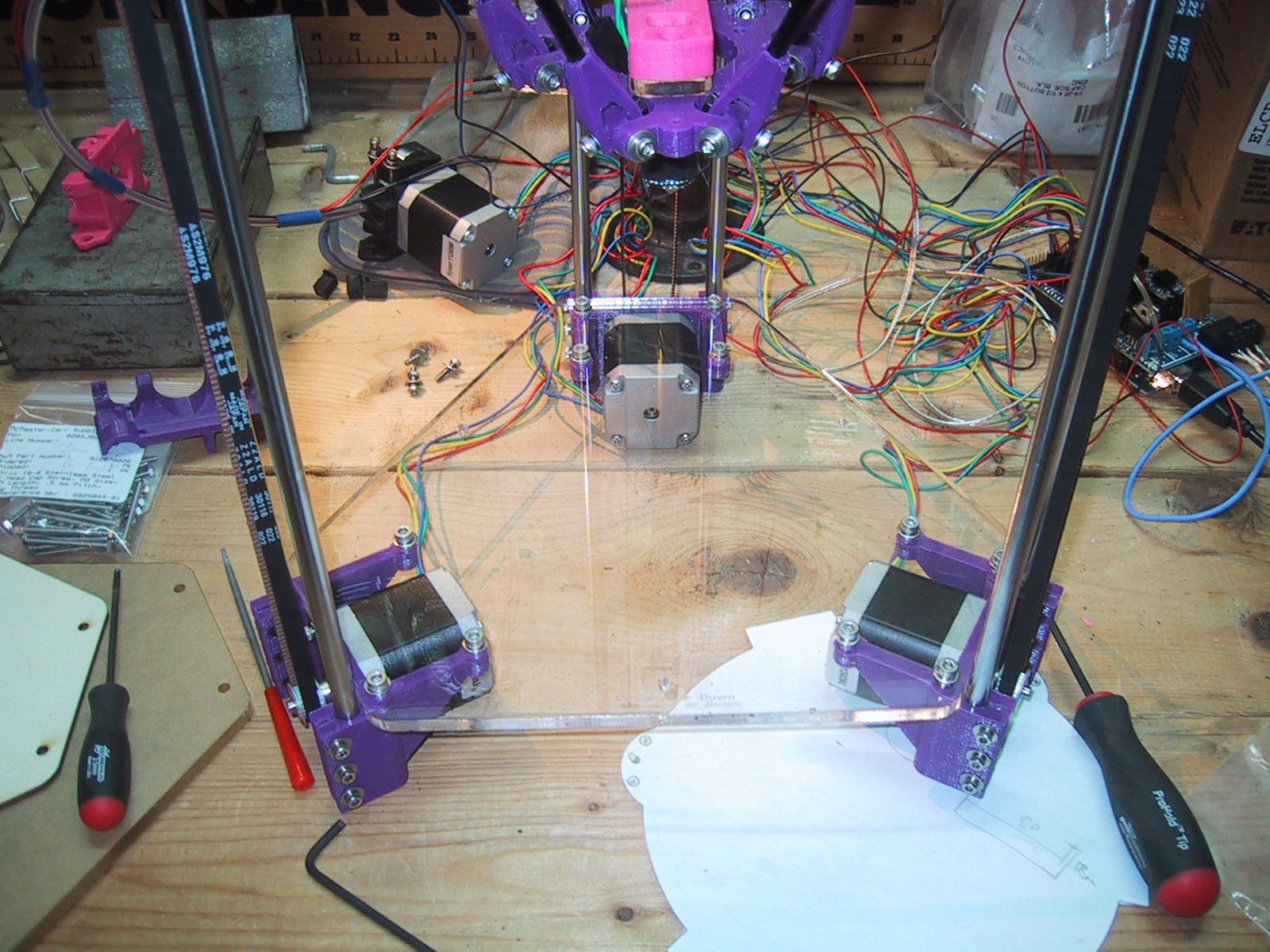
First, I swapped out the stepper motor brackets (which also serve as the legs) with three I had designed and printed that were 20mm taller. I have a full RAMPS board under the base plate of the rostock-mini, and although it fits, the fit was “very close”. I didn’t like the fact that my stepper motor wires would touch the surface the printer was sitting on, and the limited airflow paths. This extra 20mm really helps things out, and also opens up the possibility of installing an LCD control panel under the base plate in the front. (If I can figure out how to avoid my bed leveling knobs.)

Second, I upgraded the springs on my adjustable print bed to some that were a bit taller and a bit stiffer. My overall build volume was shortened from 187mm to 185mm, but now I have a lot more range for adjustments and the bed is more rigid (while still allowing the print head to push the spring loaded bed down if it crashes horribly).

wiring harness
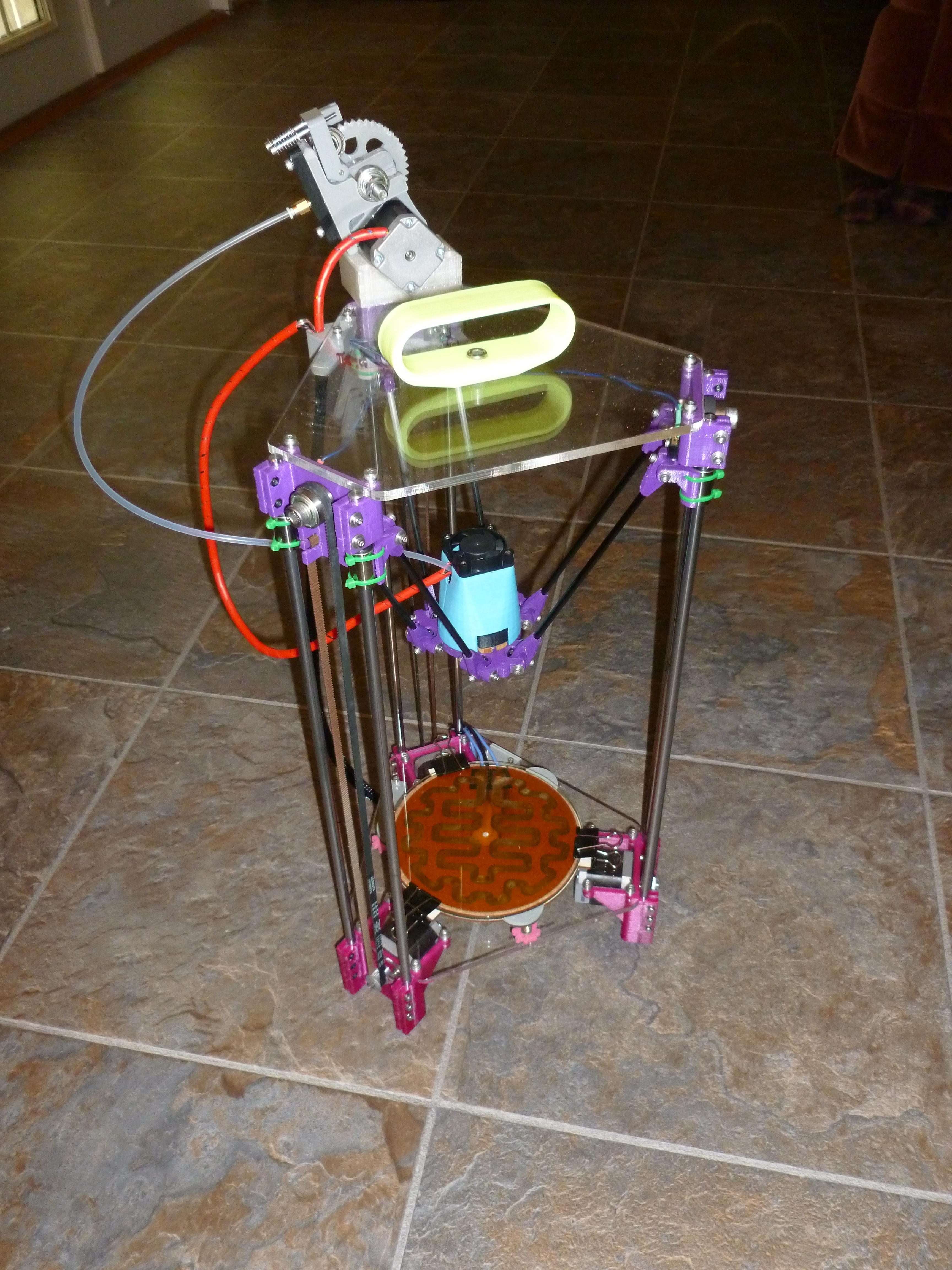
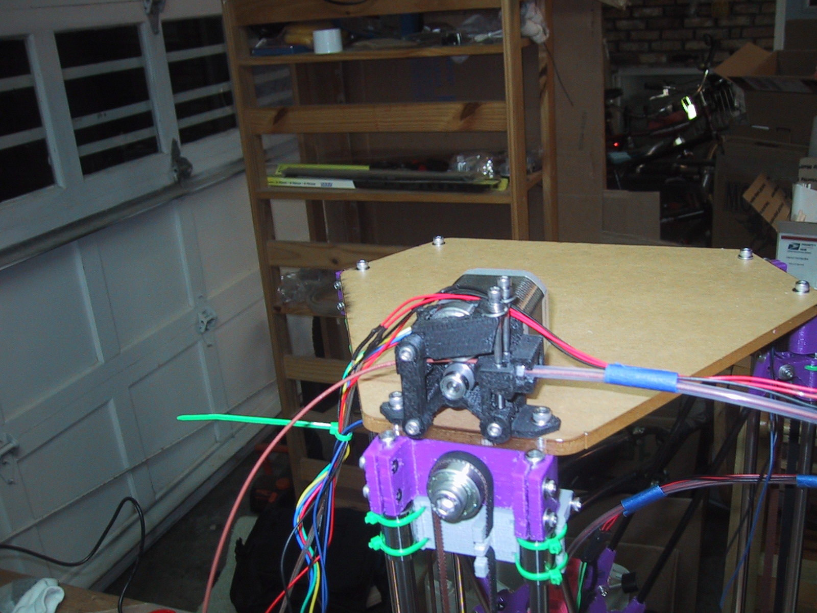
Third, I wrapped some plastic spiral wire harness wrap around the wires leading down to the print head, to give them a better visual appearance.

bowden tube ptc
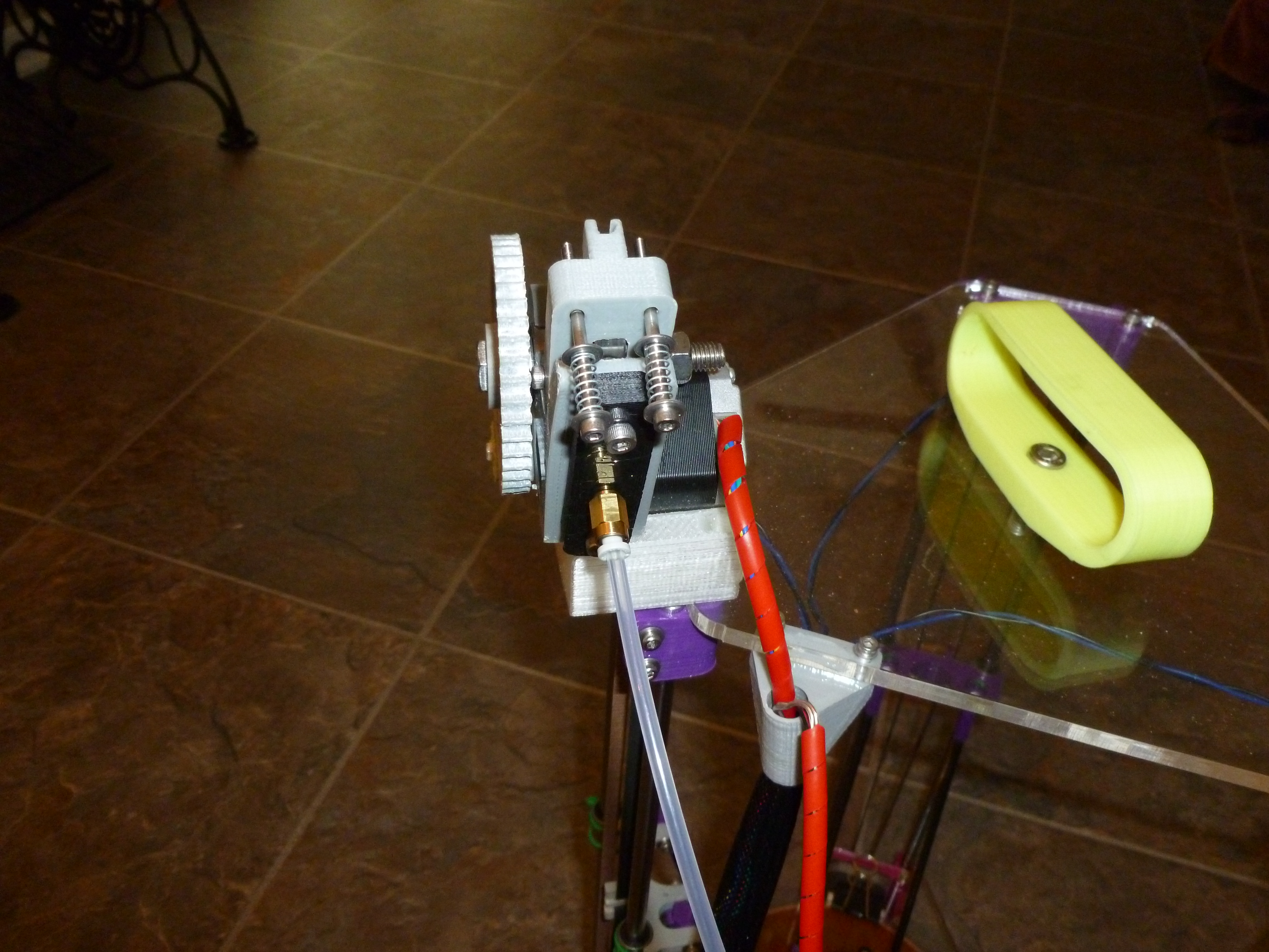
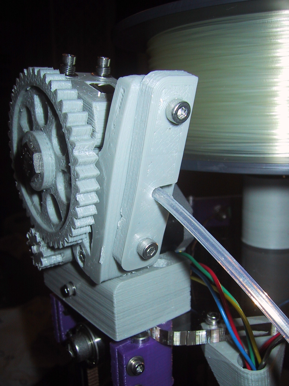
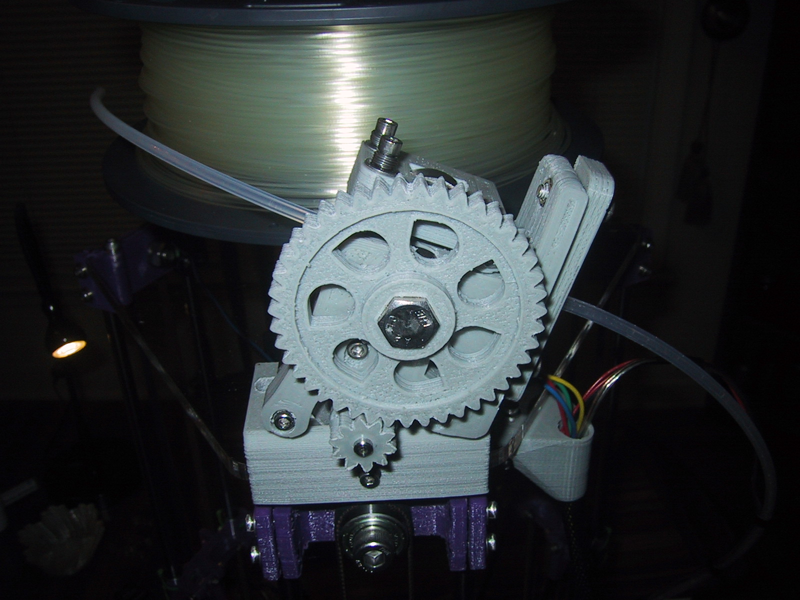
Finally, I changed out my bowden tube from using M4 nuts to hold the tube to using screw in Push To Connect adapters. The goal was to allow me to remove the tube from either end without having to unscrew the plastic part holding the nut in place. However, the cheap PTC adapters I bought appear to be single use, in that they don’t release the tube reliably without breaking, so basically it just makes the bowden tube look slightly more professional.

Yoda Bust(s)

I have been printing Yoda busts on my Rostock Mini.
yoda_on_printer

The first (small) sized one printed very well, but I had some problems when I tried scaling up to 160% size.
largeYodaHead

If you look closely, it has a small discontinuity just above the eyes. (It looks like the top of his head was sliced off and put back on slightly “off”.)
yoda_medium_slice

It looks like one of my axis lost a step, so I ran through various diagnostics (more airflow over the stepper drivers, higher current to the steppers, upgrading my slicing software, etc) and eventually the problem got worse:
lobotomized_yoda

Then I heard some squeaking from my 3D printer and started to move things around manually to isolate it and I realized that my straight rods and linear bearings were dry. The final solution was to oil my straight rod and liner bearings, although I can’t confirm that the upgrade to Slic3r didn’t also help things out. All in all, it only took four tries to get things right:

four_yodas

So now I have a large yoda head to float on my desktop levitation box:
floating_yada_head

Top speed 275 mm / sec

Although my print head can move at 300 mm/sec, my extruder can not reliably keep the plastic flowing at that speed. (Perhaps if I turned up my extruder temperature above 195 C…)

I have decided that 275 mm / sec is a reliable top speed for my extruder after printing a relatively large part at that speed with the temperature turned up to 200 C.

This video shows layers being printed in about 15 seconds with 3 exterior perimeters and 25% infill.

Here is another video of the twisted koch snowflake vase (scaled up to 150%) being printed at 275 mm/sec top speed. Due to the fractal nature of the sides of the vase the platform rarely got up to the top speed, as it never had a long enough path to accelerate up to full speed.

Printing at 300mm/sec

I decided that I needed to switch to a different (larger) 3D object so that my printer could accelerate up to full speed on some long straightaways. Here is what 300 mm/sec printing looks like on a larger square object:

However, my extruder just couldn’t keep the plastic flowing (at least, not at 185 C), and it jammed. So I have decided to try 275 mm/sec with the temp set to 200 C (lading to an actual extruder temp that is closer to 195 C).

Stepping up the speed on my Rostock-Mini

Now that my Rostock-Mini is basically finished, I have been adjusting the parameters of Slic3r to increase the print speed. Why? Because this is my sports car 3D printer….It’s small, looks cool, and is fast! In contrast, my Prussa Mendel is the family mini-van: Nothing to look at, reliable, with a large print volume.

finished_frontview

Because the Rostock-Mini has the cold end of my extruder mounted on top of the frame (not on the motion platform) it doesn’t have to move the weight of the extruder stepper, gears and associated hardware. The filament is pushed down to the platform via a bowden tube (think bicycle brake cable) and the only part that needs to accelerate and decelerate is the hot-end and associated fan / air duct. The lighter the platform is, the faster it can move and change direction while maintaining positional accuracy.

The Twisted Kochflake vase that I’ve been using for my test print has 7 layers at the bottom with “infill” but above that, it’s just made up of four perimeters of plastic traced around the volume of the interior of the vase. This means that some layers require a relatively short amount of motion/time, especially near the lower part of the vase. I have my Slic3r software set up to not allow any layer to take less than 15 seconds to give the plastic a bit of time to solidify before we put the next layer on top of it, so in some parts of the videos below the platform is not moving at it’s true top speed because of this software limitation. Also, due to acceleration constraints, the platform can’t get up to full speed on small bumpy surfaces. When the printer is printing the bottom seven layers (you’ll see it going back and forth to fill in the circle with plastic) or the wider part of the fractal pattern as the vase grows up you’ll see where layers take longer than 15 seconds (4 times around the vase is a single layer) and the platform will be moving at top speed.

Here is my printer set to 225 mm/sec, which is faster than most printers that have a moving single extruder will be able to do:

Here is the twisted Koch Vase at 150 mm/sec, which is approaching the top speed of most gantry style homebrew 3D printers that move the cold end of the extruder.

This is a relatively slow 75 mm/second video:

Rostock Mini Z-Axis accuracy

When calibrating the bed of a standard 3D printer, you can slide a piece of paper under the extruder and adjust the bed until it’s touching the extruder (but still able to be pulled out) in several places to level the bed about right. However, with a delta bot, your X/Y/Z coordinate system must be converted mathematically into the coordinate system of the three carriages ridding the towers, and determining if your calibration parameters are correct is not as easy. If your calibration parameters are incorrect, your entire coordinate space may be warped!

I was able to eyeball things to get my calibration parameters set up “good enough” for standard use, but it still wasn’t perfect. I finally broke down and shelled out $15 for a cheap Chinese made machinist’s dial indicator so that I could get my coordinate space transforms square and flat down to a thousandths of an inch. (I changed one calibration parameter by 0.5 mm…so it wasn’t terribly far off from the “eyeball” approach, but I feel better about it now…)

Here is a video of the machinist’s dial indicator in action:

The nine small vertical “bumps” in the beginning of the video is from me pushing the 0.1mm down button on the control interface multiple times until I got the indicator close to the top of the dial. As you can see from the dial it takes nine 0.1mm bumps to travel around 3.5 hundredths of an inch. Google says that 0.9mm = 0.0354331 inches, so my units appear to line up right.

I also jumped the head up and down 10mm at a time to show that the head comes back to the same Z height.

When I scrape the probe back and forth in the Y axis the indicator jiggles around due to friction, but you can see that the measurements don’t move more than 0.01″ when the probe moved across the entire glass build plate (and it’s very close to 0.001″ accuracy when stopped at the end and middle points). Overall I’m very happy with the positional accuracy and calibration of the motion platform now. Although I only measured the Z axis with my dial indicator, because it’s a delta-bot the z-axis is a joint effort of all three towers, so I figure that my positioning accuracy in the Z coordinate axis is a good proxy for the X and Y coordinate axis as well.

Greg’s Wade Bowden Extruder for Rostock-Mini

The original direct drive Airtripper V3 extruder that I had made for my Rostock-Mini was almost able to get the job done. However, my stepper just didn’t quite have enough torque to push the filament directly, and it would “skip” steps relatively continuously. I could still print large objects, but they would have a “foamy” appearance due to using less plastic than they really should. Also, my stepper motor and drivers were getting hot due to all the extra current flowing through them.

I finally decided it just wasn’t going to work well enough for production use, and printed an extruder (Gregs Accessible Wade extruder) that has a printed gear system for a large mechanical advantage. I adapted it to feed into my Bowden tube and mount onto the top of my Rostock-mini frame with two printed parts.
IMG_1250

It made all the difference in the world. My geared extruder can now easily feed filament continuously through the hot end at a 300mm/min rate.

I also printed an adapter plate that holds the stepper motor and attached extruder in the appropriate location/angle. In the future I may integrate this with parts from Gregs Wade extruder design to build an integrated extruder.
IMG_1247

Finishing the Rostock-Mini

I find that getting a 3D printer working (i.e. printing parts) is relatively straightforward. But getting it FINISHED takes just as much time. Over the last month I have been working on finalizing all of the little bits of my Rostock-Mini that will take it from a “working printer” to something I am willing to put on a desktop and show off.

First, I needed a spool roller. I could have mounted the spool beside the printer on top of one of the many tabletop bearing spool rollers on Thingiverse, but I really wanted the footprint of the printer to be self contained, so I decided to mount the spool horizontally above the printer, and of course, designed my own horizontal spool roller system.

complete_sr_with_short_ER_ring

The biggest threat to a “finished” look is wires. Lots and lots of wires. Lets count them up… 4 per servo (16 so far), 2 per end stop (6 more makes 24!), 2 for each heater (extruder/bed) and temp sensor (extruder/bed) and fan (10 more make 34!) plus a few more to power the whole thing!

I tackled the power inlet and power switch (a.k.a. Emergency stop!) first, by designing a power inlet block to fit my jack and switch. Although not taking full advantage of the medium, I’ve found that 3D printers do a good job making custom front panels.

final_installed

I shortened all of the wires under the base to size and then covered the servos and power wires with a wire mesh. (Wire management, in the form of extra crimp receptacles so that I could make custom wire lengths and wire mesh added $30 to the project cost…and quite a bit of time. After an hours work with my smallest needle nose pliers, I’ll be quite happy to outsource the population of crimp connectors.)

under_base_wireing mesh_wiring_keepers

Luckily, with the Rostock-Mini, a good number of the wires are under the base, but even if you didn’t choose to put your extruder servo up top like I did, you’d still have to deal with getting quite a few wires from the endstops and print head down to the base. My current plan is a big long length of wire mesh. (Did I mention that I like this stuff?)

Rostock-Mini: Fully Operational

After replacing the 1/8″ plywood temporary base and top frame plates with the final 1/4″ acrylic , my rostock-mini is working very well! The extra rigidity in the frame has greatly improved it’s positioning accuracy and it’s making prints that rival my Prussa Mendel for quality. The video above shows my round print bed and spring loaded adjustable levelers in action, as well as a close up of the delta bot motion.

This is a picture of the clear acrylic base plate before I added the print bed holder to it.
clear_acrylic_base

Here is the complete printer with the adjustable print bed.
working_printer

I mounted the airtripper v3 bowden extruder cold end on the rear of the top plate. As it turns out, the M6 screw holes on the extruder are close enough to the right distance apart to match up with the idler top end printed bracket, so I can use the same M4 screws (with fender washers) to hold the extruder cold end as well as hold the top plate to the idler bracket! Once I saw that bit of luck I gave up all thoughts of mounting the extruder under the bottom frame plate.

airtripper_extruder_on_top