Curtis 1231c upgrade: Binning Gate Drive Resistors

I am upgrading the power board of my Curtis 1231c DC PWM motor controller. It uses 18 MOSFETs to switch the power, and each MOSFET had a 47 ohm resistor on it’s gate input. The point of such a high resistance was to slow down the switching of the MOSFET’s so that they would all share the current somewhat equally and no single MOSFET would turn completely on before all of the others had a chance to start shouldering the load.

Continue reading

Curtis 1231c Power Board desoldering

I desoldered all of the main power components (diodes, MOSFETS, capacitors) from the power board of my failed Curtis 1231c PWM DC motor controller. The plan is to upgrade all of the components to give it higher capacity; while producing less heat. Of course, to replace them, I had to remove the old ones, which took around 6 hours of work with two different soldering irons and a solder sucker.

My advice:
-Heat component legs (diodes/MOSFETS) from the top of the board (side with the component) while you solder-suck from the bottom. Get one leg completely free first, then work on the other. After you suck almost all the solder out, you may still need to re-heat the leg and push it away from the PCB with a small screwdriver so it doesn’t stick to the inside of the hole.
-For the capacitors, don’t be afraid to add a little solder to the smaller leg, and then use a 100 Watt super wide tip soldering iron to heat both legs up at the same time, and pull the capacitor straight out. Suck the solder from each hole individually later once all the components are gone.
-I heartily recommend the Engineers SS-02 Solder Sucker, the silicon tube it uses is great! I did get solder stuck inside the metal tip a few times, but nothing a 5/64th drill couldn’t fix right up.
Continue reading

Curtis 1231c diodes: Diotec DR7506FR vs TSR2402R

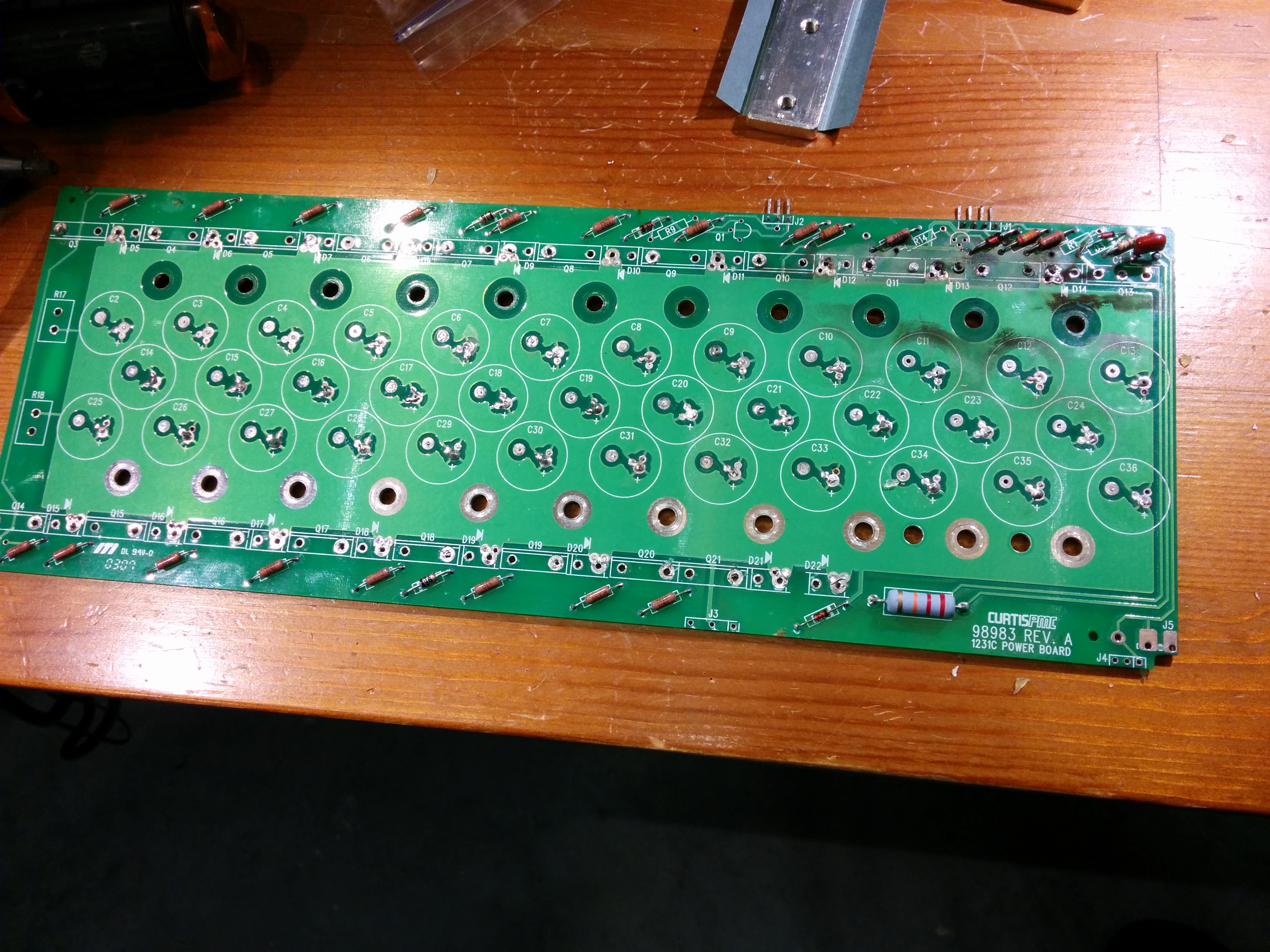
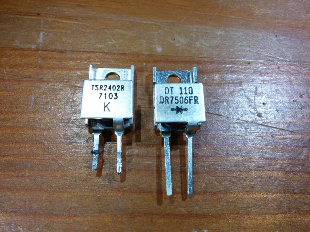
I am looking to replace the MOSFETS, diodes, and capacitors in my Curtis 1231c with upgraded components. I unsoldered one of the existing TSR2402R (7103 K) diodes from the power board and tested it with my Fluke meter and bench power supply.

Here are my results:
Power Supply providing 3.2A, forward voltage drop: 0.776 volts
Power Supply providing 2.0A, forward voltage drop: 0.737 volts
Power Supply providing 1.0A, forward voltage drop: 0.697 volts
Fluke Diode Setting: 0.351 vdc

Average time for the button temperature to raise from 25 °C to 50 °C with a 3.2A current: 45 seconds

The replacement parts I purchased were from DIOTEC, specifically their DR7506FR model (the R at the end means “Reverse Polarity”, making them an exact drop in replacement in form factor and polarity). They were marked: “DT110   DR7506FR” plus a diode schematic. Here are my results for the upgraded component:

Power Supply providing 3.2A, forward voltage drop: 0.754 volts
Power Supply providing 2.0A, forward voltage drop: 0.700 volts
Power Supply providing 1.0A, forward voltage drop: 0.646 volts
Fluke Diode Setting: 0.399 vdc

Average time for the button temperature to raise from 25 °C to 50°C with a 3.2A current: 47.5 seconds

Of course, the original diode I’m measuring had been in use for many years (I estimate ~750 hours of driving time given the 22K miles) and was heated up as part of the soldering and unsoldering process, while the DR7506FR I tested was brand new straight from the manufacturer. After I unsolder a few more diodes I’ll check them to make sure their readings are similar. (I’ll probably also test a few other DR7506FR diodes from the bag as well.)

Of all the measurements, the temperature rise time measurement was the least scientific, as I was using an inexpensive non-contact IR thermometer and attempting to point it at a small button in each diode, waving it back and forth to find the hottest temperature. I took 4 measurements on each diode (alternating to let the other one cool down) and averaged them together. In general, the readings from the DR7506FR were longer than from the original TSR2402R with one exception. If I throw out that pair of readings, the averages would be 46 seconds vs 50 seconds. Given that the measured forward voltage drop for the DR7506FR was lower for any real amperage readings, it dissipating less power and taking longer to rise to 50 °C appears to be reasonable.

Curtis 1231C-8601 500A PWM DC Motor Controller teardown

After replacing the Curtis 1231C-8601 motor controller that had failed, I opened the case up to figure out what had failed.   The controller hardware is inside of an aluminum extrusion with both ends “potted” with some black semi-flexible material (hard silicon perhaps?) that could be cut using a razor knife and a lot of effort.


Inside, there is a Pi shaped piece of aluminum extrusion that acts as the heatsink for the MOSFETS and freewheeling diodes, as well as being electrically connected to the motor – terminal. It is held against a large thermally conductive, but electrically insulating pad, which separates it from the controller case, but allows heat to be dissipated. It is held in place with 8 screws that pass through insulating plastic brackets into the bottom of the case.

People online had told me that these screw holes were “potted”, but on my controller they were just filled with two rubber plugs.They also told me that you could not cut through the Curtis potting material with a razor knife. [This super hard potting material was also prone to cracking at the edges and letting moisture into the controller, so a flexible rubber like material is better anyways…]

Continue reading