Mounting Ring Floodlight Cam under an eave

I’ve been happy with my Ring Doorbell camera, and when one of our motion lights stopped working, I decided I wanted to use the Ring motion detecting Floodlight Camera to replace it. The only problem is that the Ring Floodlight Camera is designed to be wall mounted (about 8′ high) and Ring specifically says it can’t be mounted under an eave. Challenge accepted.

As It turns out, you CAN mount a ring floodlight cam under an eave, but unless your eve is flat the camera part doesn’t have quite enough play in the provided ball joint.   (My eve follows the upward slope of my roof.) To fix this, you need to loosen the retaining screw, pop the camera unit out of the ball joint, and then grind a notch that will allow it to swivel upwards (formerly downwards) just a bit more.

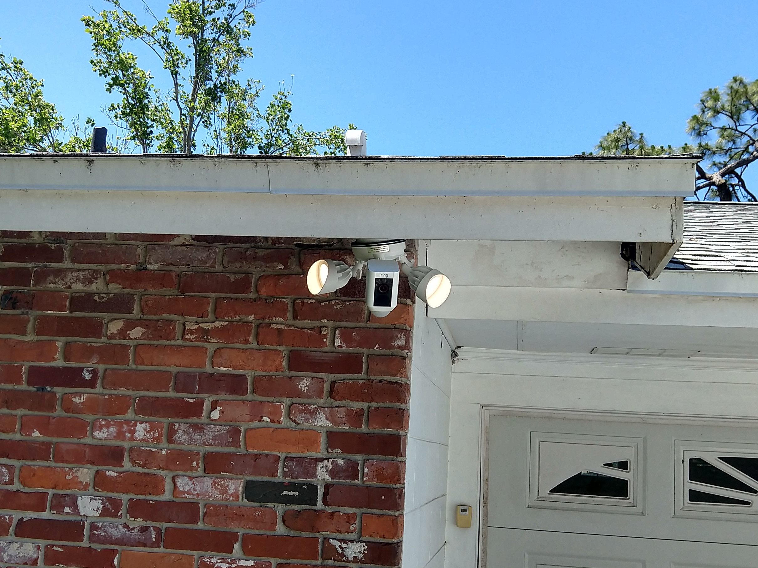
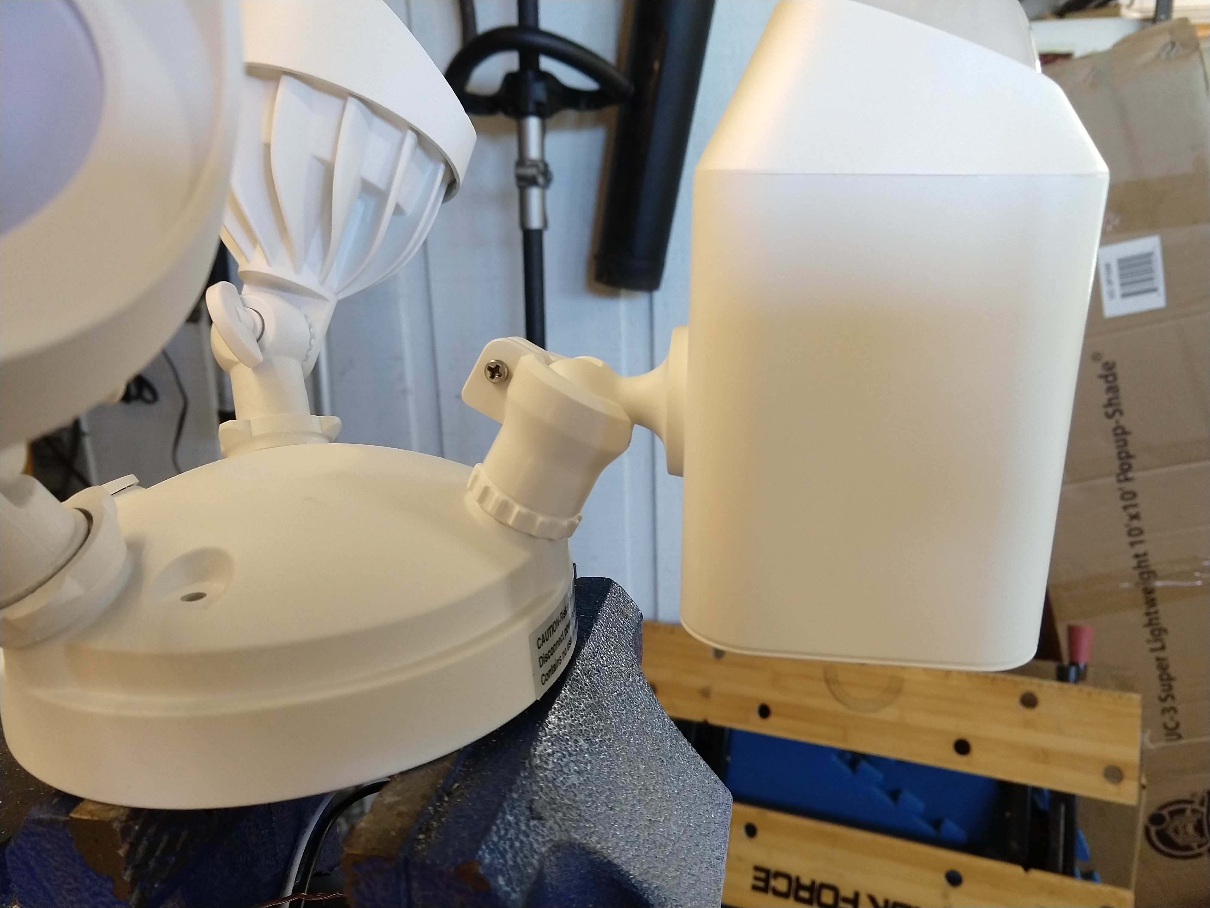
The end result looks like this:

Here you can see the notch I ground out of the ball joint:


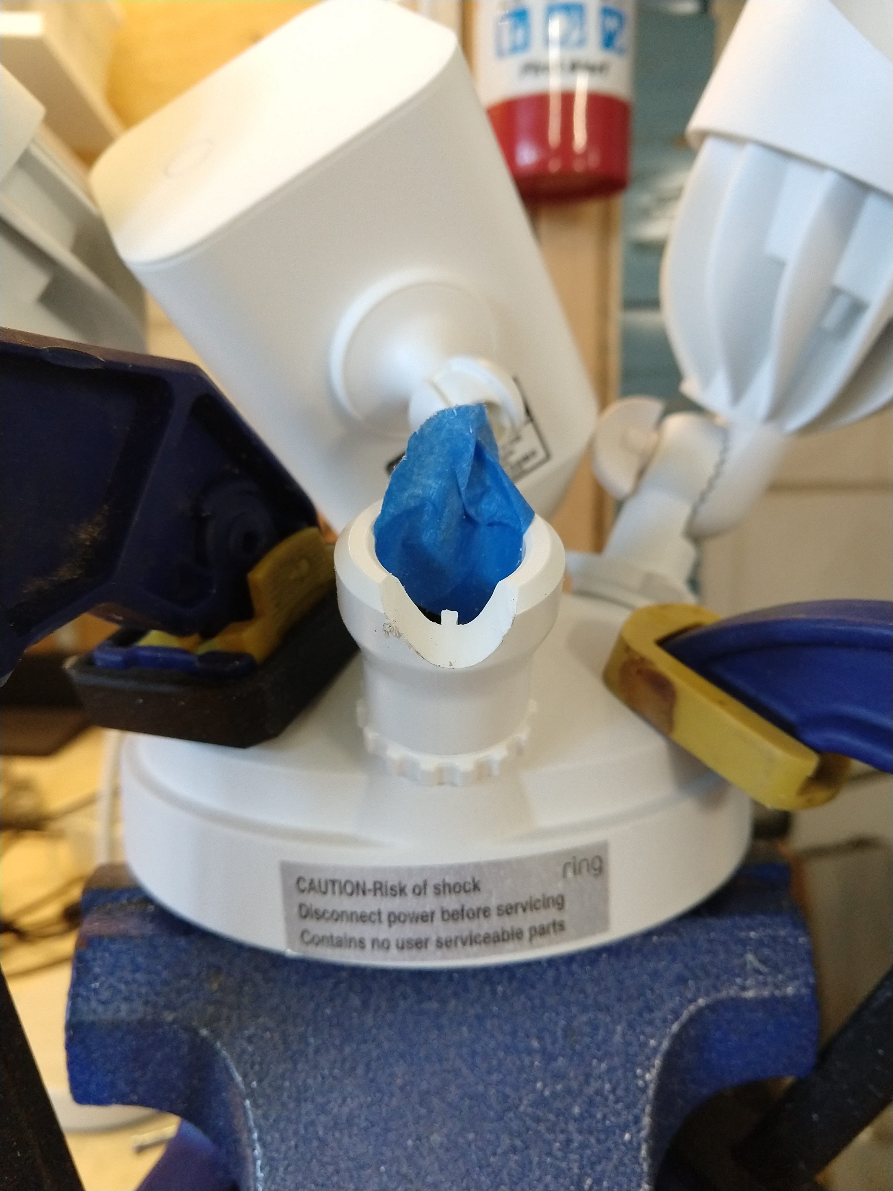
I used an angle grinder with a grinding wheel, but the plastic is soft, so you could do it with a rotary tool or even with a file by hand if you had a lot of extra time. Note the masking tape to make sure the camera cable stayed well out of the way of the grinding wheel.

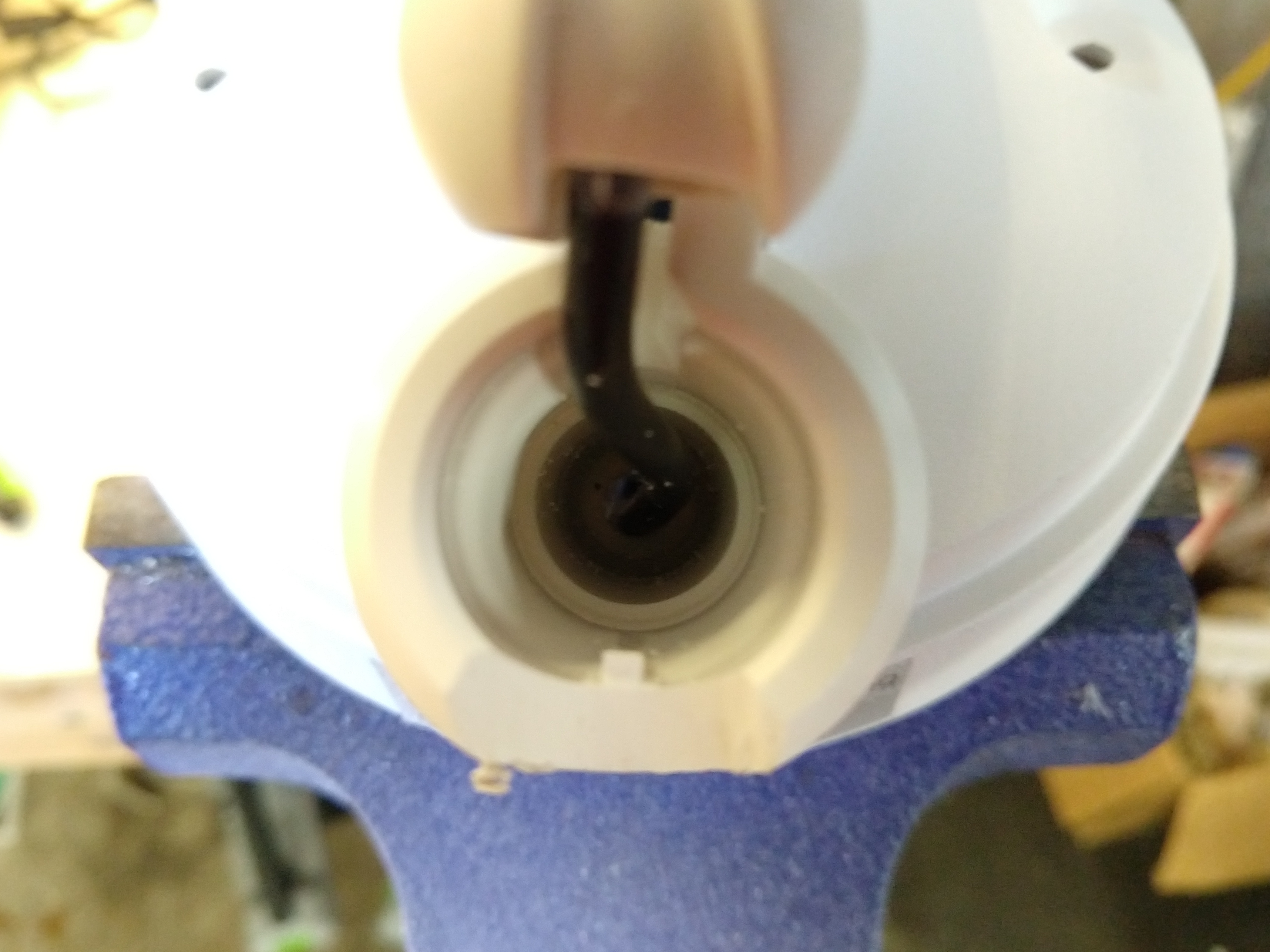
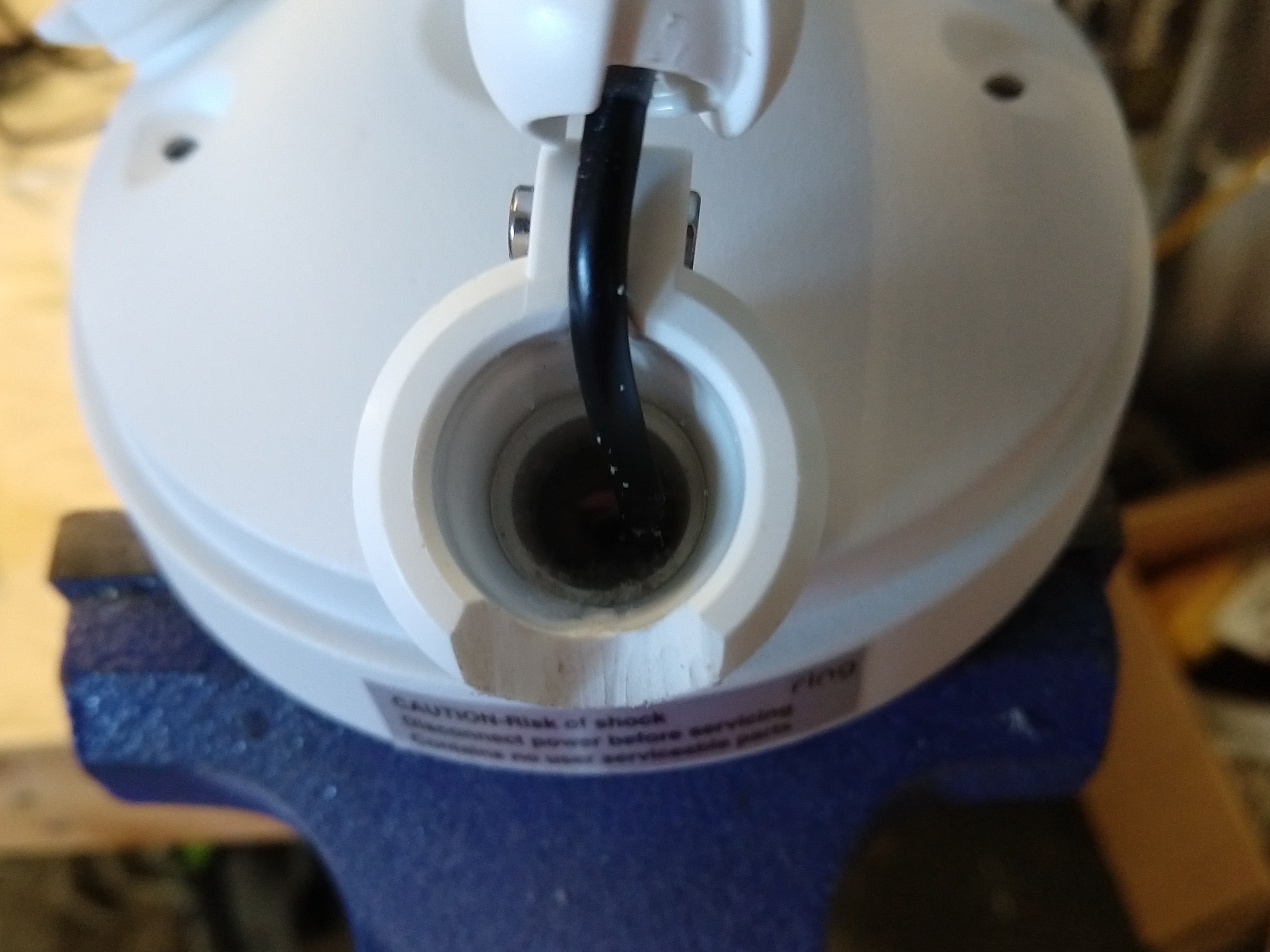
There is an internal square tab inside the ball joint, which also has to be filed down (I used a hand file for this one):

After this small modification to the ball joint, there was plenty of flexibility to aim the camera exactly where I wanted it and have the bottom of the motion sensing pod level with the ground. Of course, you will need to rotate the lights so they are not “upside down”, so the “rain shields” are correctly on the top.   [Note that the camera part is shipped “upside down” in the box, and normally you would need to flip it over when wall mounting, so you can omit that step.]

I am lucky, in that I have a low roof, so that the angle of the camera is still right around where it should be for capturing good images of faces. If you had a two story house, mounting a camera under the eave wouldn’t give you a very good angle.

Does this modification void the warranty? Possibly. If the device fails due to this modification, it would certainly void the warranty. [For example, if the camera unit falls out and breaks after I modify the ball joint designed to hold it.]   However, if the camera unit were to fail due due to an electronic or software problem completely unrelated to the modified ball joint, the Magnuson-Moss Warranty Act could give me legal standing to insist that Ring replace/repair the camera unit because its failure was unrelated to my modification.   [I’m hoping the situation doesn’t come up….I made sure to test the floodlight camera before I broke out my angle grinder to make sure everything was working right before I started hacking on the ball joint.]

Banshee sailboat rudder & tiller rigging

This is my new (to me) Banshee sailing dinghy. She is 13 feet overall, and cat rigged, which means she only has a single sail behind the main mast, with no head sail. This rudder and tiller doesn’t look exactly like that shown in photos online of other Banshee boats, so it may be a later retrofit.

This is how I rigged up the rudder and tiller. All of the attachment points were already there when I got the boat, but I added two bungee cords and an up-haul line. I have no idea if this is the “official” method, but it seems to work for me.

First, I wrapped a 24″ bungee around the tiller and secured it to this forward eye strap with a chain link and then attached it to these pre-existing eye straps on the inside of the transom. This gives an automatic “return to center” action for the rudder.

I used a 42″ yellow bungee cord wrapped in the middle around an existing bolt
in the front of the rudder to pull and keep the rudder down, while at the
same time, allowing it to rotate backwards if ran aground.

I attach the ends to this front eye strap when under way, or can move them
to this rear eye strap to make the rudder easier to lift.

I used a 1/8″ line tied to an existing hole in the back and of the rudder and routed around the tiller to a bottom mounted jam cleat to raise the rudder. It’s certainly possible that this jam cleat is really intended for a down-haul line, and not an up-haul line, as it’s on the bottom of the tiller.

So, that’s what I’ve done, it works for me, but feel free to leave a comment if I’ve completely messed things up.

Philips Norelco QT4085 beard trimmer disassembly and battery replacement

My trusty (yet old) beard trimmer has needed to be plugged in to use for a long while now, but the batteries finally degraded so much (I suspect they were a direct short) that even plugging it into its charger failed to make it work. So, I took it apart and replaced the batteries. (They needed it, I believe they were from 2001.)

This video distills what I learned (the hard way) about the proper order of operations for disassembling this model to get to the battery to replace it.

Tektronix PWS4721 power supply teardown / diagnostics / repair

I broke my PWS4721 power supply by connecting it to a battery and driving current back into it. (I don’t remember if I reversed the polarity, or just had the output voltage lower than the battery voltage.) The end result was that the power supply had it’s output shorted internally, so that the output voltage was always near zero, and the current was right at the maximum current limit but no power was coming out of the front (or back) connections.

The broken component turned out to be Diode D408 on the main circuit board right in front of the power output header. It appears to be a reverse polarity protection diode, so it’s likely that I accidentally reversed the leads when connecting to the battery (all I remember is the spark). This diode is a 1N5408 (general purpose 1000 volt 3 amp diode) which I was able to replace for $0.40 (Although my total cost was closer to $10, as I ended up buying 10 of them just to have a few more sitting around if needed, and shipping cost me $4.33 from Digikey.) The only specialized tool I needed was a Trox-10 (t-10) screwdriver to remove the security (star) screws from the factory maintenance port so I could remove the back panel.

Of course, I had to disassemble the entire unit to get to the bottom of this circuit board to make de-soldering and diagnosis easier.   The output power rails were shorted before I removed the diode, and were NOT shorted after I removed it, and the diode had failed shorted, conducting in both directions.

In retrospect, I could have probably desoldered the diode in place from the top of the circuit board (the long lead would have been easy, and since the diode was already ruined, I could have heated up the body and pulled the whole thing out from the top and then replaced it without removing the entire circuit board. But, at the time, I wanted access to the rest of the circuit board just in case the diode wasn’t the (only) problem.

You know it’s a high quality piece of equipment because in addition to checking that it worked, they let it burn in to find out if any parts were going to fail quickly, and then calibrated it!

If you want to see how to tear down a PWS4721 and what is inside, here is the video:


And a few photos of the main board with heatsync and top logic board: