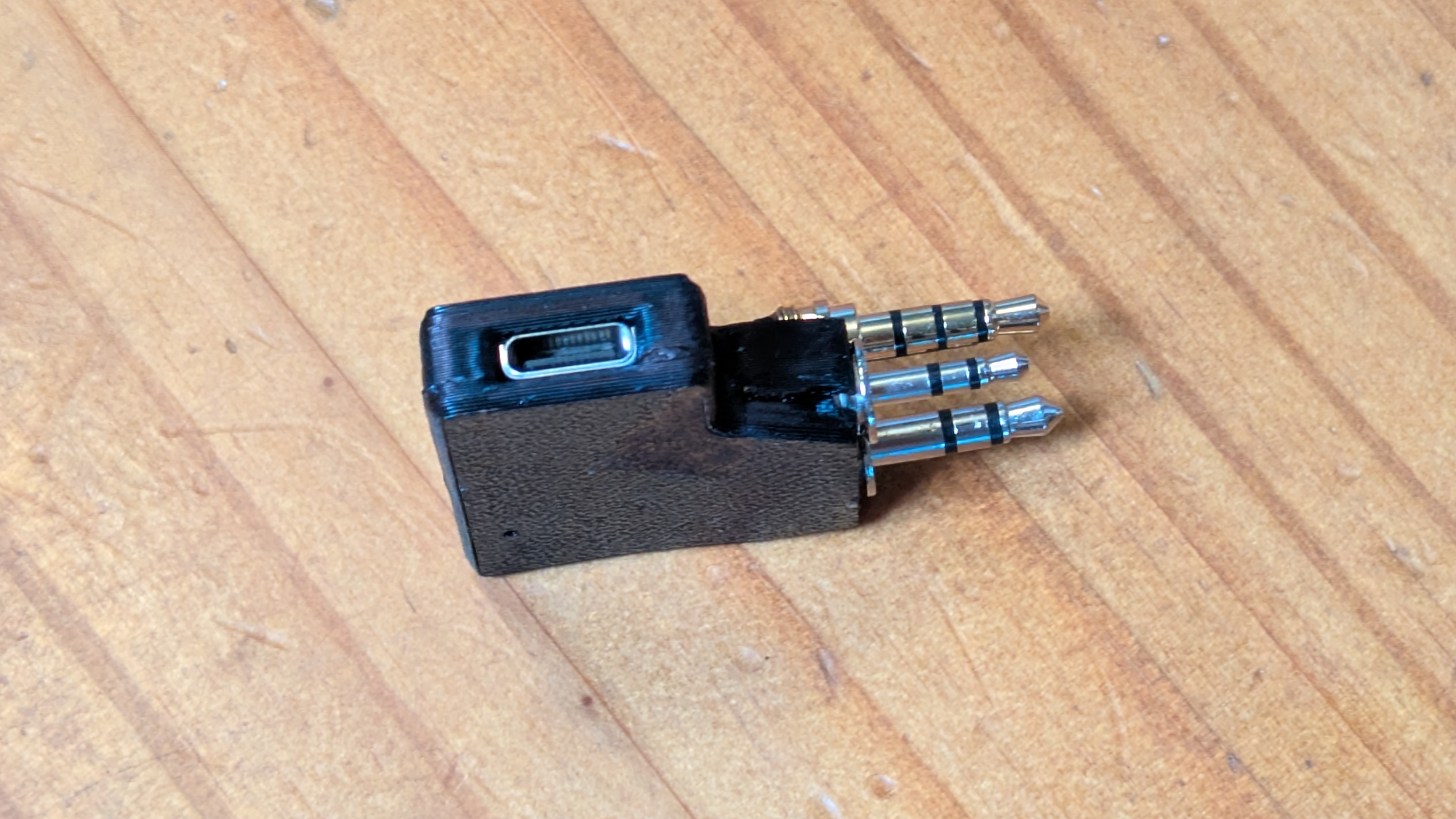
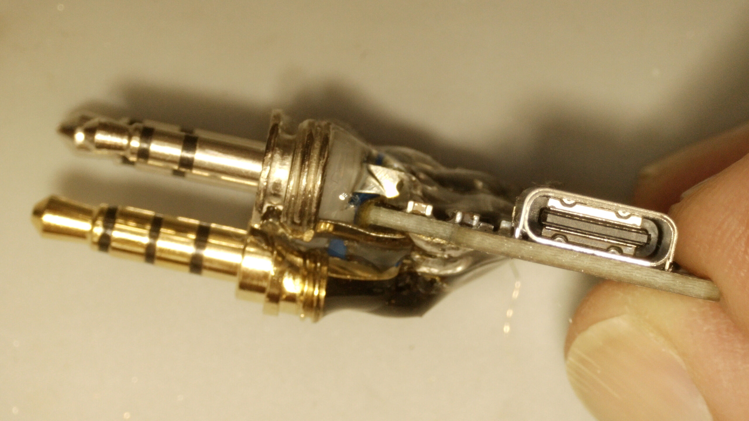
I added a 3rd 3.5mm plug to the open hardware AIOC sold by NA6D to send the serial data to the CAT port on my uSDX+ SDR radio.
I added a 3rd 3.5mm plug to the open hardware AIOC sold by NA6D to send the serial data to the CAT port on my uSDX+ SDR radio.
The iCom IC-725 Transceiver receives CW (Morse Code) natively, but you can install an optional “narrow” CW filter that gives you greater sensitivity / out of band rejection.
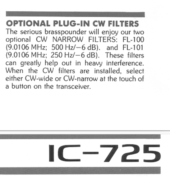
The FL-100 (500Hz notch) or FL-101 (250 Hz notch) are suggested in the IC-725 manual. I instead installed a FL-232 (350Hz) filter which is designed for later ICOM radios, but has the same form factor, and is designed for the same 9.01 Mhz IF that the IC-725 uses. This is a “happy medium” between the 500 and 250 sizes (Plus, I found a FL-232 for sale at $87 shipped, while most of the FL-100 and FL-101’s I’ve seen for sale are $120-150 shipped from Japan.)
My forward power meter was not moving at all, and it later turned out that the reverse meter wasn’t moving correctly. The root cause was that both of the diodes in the meter circuit had blown (Not sure why, perhaps somebody put a LOT of watts through the unit? Apparently this is a common cause of problems for the meters on MFJ tuners from this era).
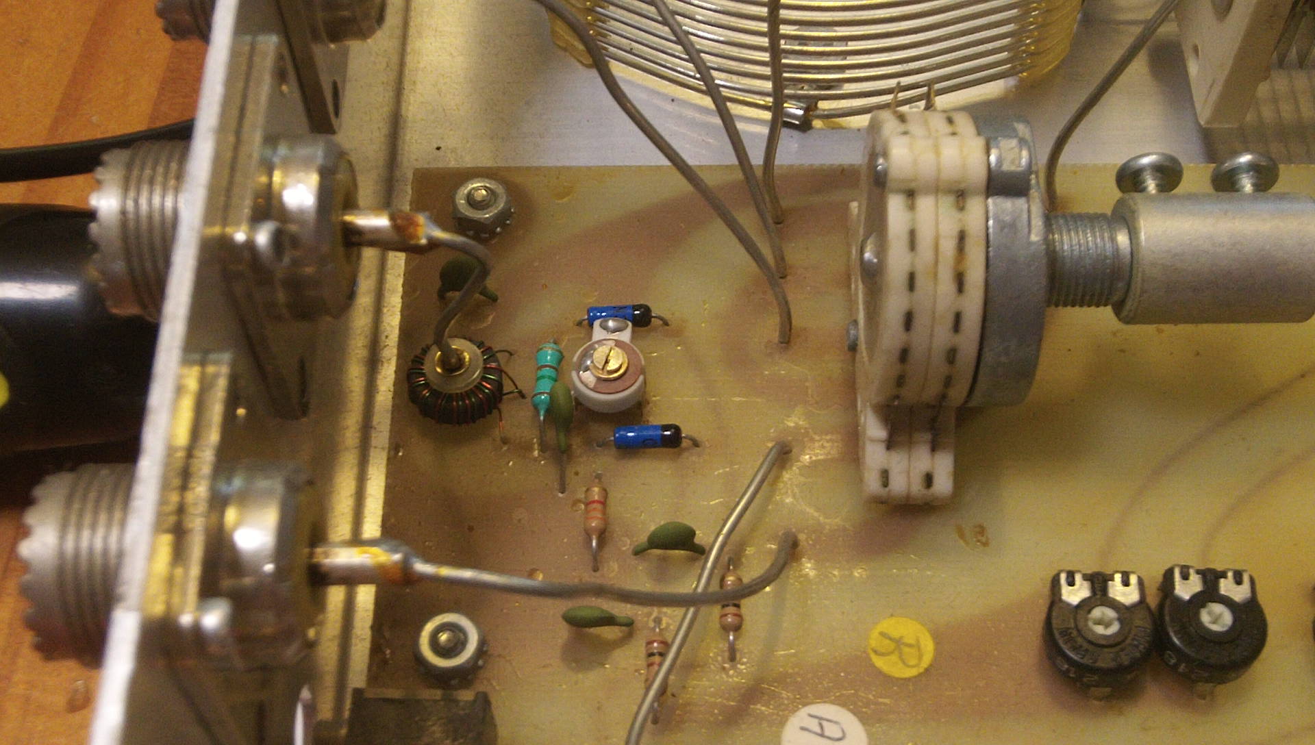
The final solution was to replace both diodes (the forward diode had failed open, and the reverse diode had failed “closed” but not working as a diode properly so some forward current was going through it to mess up the reflected power reading).
These 1N34A Germanium diodes appear to work as well as the OEM diodes, even though they are not the blue/black color scheme and are physically smaller.
I didn’t want to unsolder all of the PL259 coax jacks and take the front cover & knobs off just to get access to the trace side of the circuit board, so I instead soldered the new diodes to the legs of the old diodes (so the old diode body would keep the legs from falling down if the solder on the traces below melted) and then clipped out the old diodes. Not as clean as if I had access to the bottom of the circuit board, but a lot faster and much less likely to break the set screw threading of the 30+ year old plastic knobs.
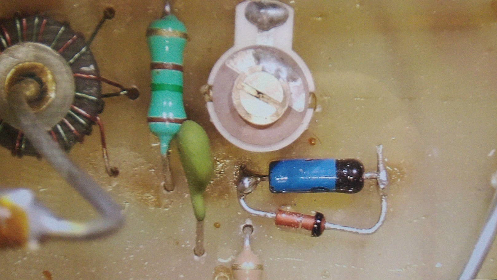
In the above image you can see one of the new diodes bypassing the old diode (before I cut away the original shorted diode). You can also see the “balance” tuning capacitor just above it, and the current sensing transformer with the transmitter feed-line going through the center at the far left.
Two of the three 12volt incandescent “grain of wheat” light bulbs in my 30 year old iCom IC-725 radio had burnt out, making it difficult to see the meter at night. (And one side of my LCD was much dimmer than the other, although it was still readable.)
Although they are soldered to the front panel circuit board, replacing them is relatively easy if you have a fine tip soldering iron and good magnifying glasses.
Access requires you remove the top and bottom covers, and then unscrew the screws holding the front cover in place (two on each side, and two on the top in the silver metal, not the two holding the plastic panel in place). This allows you to “fold” the front cover down without unplugging any wires to get just enough access to solder from the back of the circuit board.
Here is a photo of the rear of the circuit board with the locations of the three lights marked in yellow (the red dot is a 4th hole that is directly behind the LCD, and looks the same, but was unpopulated in my radio. It’s possible a light is supposed to go there in the original design, but it doesn’t look like there is any way for the light to get to the back of the LCD panel from that hole (i.e. no light guides as seen in the other two holes on the sides of the LCD).
![]()
I just held each leg of the bulbs with a pair of tweezers and pulled it out of the solder blob after heating it up with my micro tip soldering iron. To install the new bulbs, I carefully clipped the legs to length, and then pressed them into the solder blob with the tweezers. [Only in one case did I have to add a drop of my own solder to help thermal conductivity to get the original solder to melt and flow around the bulb leg.] Be careful to not drop any metallic leg clippings into your radio.
The original bulbs were very small incandescent bulbs surrounded by a yellow overlay that makes them look like LED’s, but they are NOT LED’s. If you could find some 12 volt side throwing LED lights you could use those to replace them for longer lifespan, but given that the radio is 30 years old now and only 2 of the 3 original lights burnt out, I’m hoping these replacements will last a long time.
The ones I purchased were larger than the original lights, but fit the holes fine. I got them from e-bay seller: “Affinity For Artifacts” (About $12 shipped)
Qty 5 Light Bulbs Icom IC-720 IC-721 IC-725 IC-730 IC-735 S Meter Backlight Lamp
https://www.ebay.com/itm/126120391794
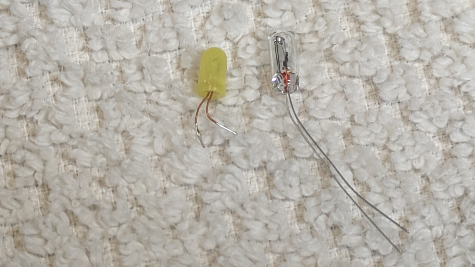
The original (yellow plastic cover) is on the left and measures:
3.35mm diameter, 6.25 mm length (plus wire leg length)
The replacements (on the right) measure: 3.74mm diameter, 10.15 mm length
(and stick out the back of the circuit board just slightly)
This photo makes the center of the LCD look darker than by eye (perhaps that mystery empty 4th hole was designed to counteract this?) but in person I didn’t find it very noticeable.
Final result
Reminder: a trans-match (commonly misnamed an “Antenna Tuner”) can NOT improve the efficiency of a bad antenna. It just matches the impedance to the 50 ohms expected by your transmitter so the transmitter doesn’t know how bad it is and doesn’t overheat. (That reflected power is still turned into heat at the antenna & tuner, just not in your expensive transmitter…) So try and tune your Antenna first, and only use a transmatch as necessary.
Button settings on an MFJ-941D front:
The 25 year old GPS module in my LX200GPS telescope has great difficulty getting a GPS fix. (My telescope is on a wedge, so the antenna is facing north instead of “up”, plus the backup battery died and is extremely difficult to replace without removing the telescope from the wedge. The biggest reason is that it is 25 years old.)
So I bought a modern BN-280 GPS module ($25) and a $10 USB->Serial TTL programmer, and replaced it. There are some technical details you need to get right to make it work (4800 baud, sending only $GPRMC messages, getting the wires hooked up right) but the overall process is relatively straightforward. Above is my howto video, and below is my big text dump:
To issue an One-Time Programmable (OTP) eFlash message in u-blox u-center use the “Messages View” to send specific binary commands to configure or flash the device.
This is done by opening the message view, selecting the CUSTOM type, pasting the command string, and sending it.
WARNING: This is a one time only, non-reversible procedure. After you blow the eFuses with these commands, the M8Q device will ALWAYS default to 4800 baud and GPS only mode on startup. (You can connect to it at 4800 baud and issue configuration messages to change this, but the next time the device is powered down without backup memory power, it will revert to the 4800 / GPS mode only defaults.)
To program 4800 baud default:
B5 62 06 41 09 00 01 01 30 81 00 00 00 00 FC FF 20
To program GPS only mode (disables GSV messages about individual satellites, reducing the total amount of data sent each second):
B5 62 06 41 09 00 01 01 31 81 00 00 00 00 01 05 2C
The above eFlash commands are not published by uBlox (they probably don’t want random people permanently changing the startup default behavior of their GPS units without understanding the irreversible nature of the command) but were provided by u-Blox technical support upon request.
WARNING to LX200GPS users: The uBlox M8Q can ONLY handle 3.3 volt TTL signaling. The Meade LX-200 holds the GPS TX pin high to 5 volts (but uses a level shifter to 3.3v for the GPS RX pin???), which has killed my TX pin (latch up) on a SAM-M8Q unit. So I’m switching over to using a Beitian BN-220 module.
Quick HOWTO on how to configure Ubuntu / Lubuntu (24.04 or later) to work with the RTL-SDL Blog $50 hardware kit (that includes a dipole antenna).
The RTL2832U chip in the v3 dongle is designed for DVB-T (European digital TV standard) and not for the ATSC standard used in North America. While these dongles are excellent for general-purpose software-defined radio, they lack the necessary bandwidth to capture the 6 MHz ATSC channel width, as they are limited to approximately 2.4–2.8 MHz of bandwidth.
If you want to go more in depth and download / install some more software, I highly recommend the “Intercept” package which makes it relatively easy to switch between a LOT of cool things to receive: https://github.com/smittix/intercept
The following commands were used to get the hardware up and running using only “repository” sources, no downloading software from github and compiling and installing anything yourself. (If you are willing to go that route, look at Intercept linked above, as its install script makes things as painless as possible.)
Continue reading
This test is both very unfair, and also fair:
First, I just placed the two telescopes outside and set them to image the same three objects for the same amount of time, and I didn’t try super hard to keep the imaging area the same. Both telescopes have mosaic modes, and if I used them, I used the android app for each telescope to “eyeball” them to be about the same general size around the target.
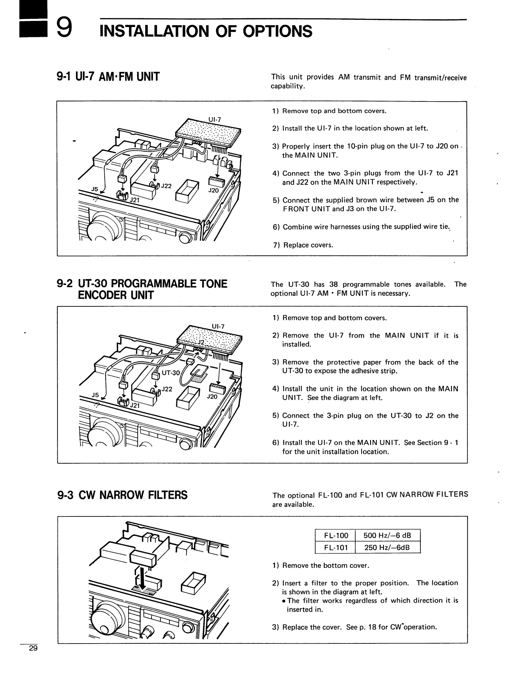
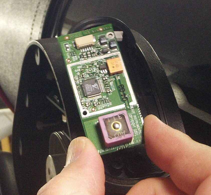
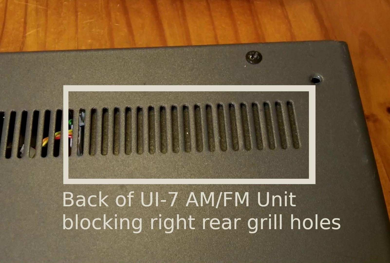
The Icom IC-725 radio has three optional expansion units that may or may not be installed.
The UI-7 AM/FM Unit allows it to operate in AM and FM modes (in addition to SSB and CW) and plugs into the bottom of the main circuit board near the rear of the unit. When it is installed, the air flow grill openings on the rear right side of the bottom of the radio will be blocked. (Looking at the radio upside down from the front/knob side)
(Empty) Location where the UI-7 AM/FM unit would be installed (also the UT-30 tone unit would go under it.
[All IC-725 radios have the FM/AM and CW/Narrow buttons on the front panel, so the existence of these buttons, or even the AM/FM icons lighting up on the LCD panel doesn’t mean anything.]
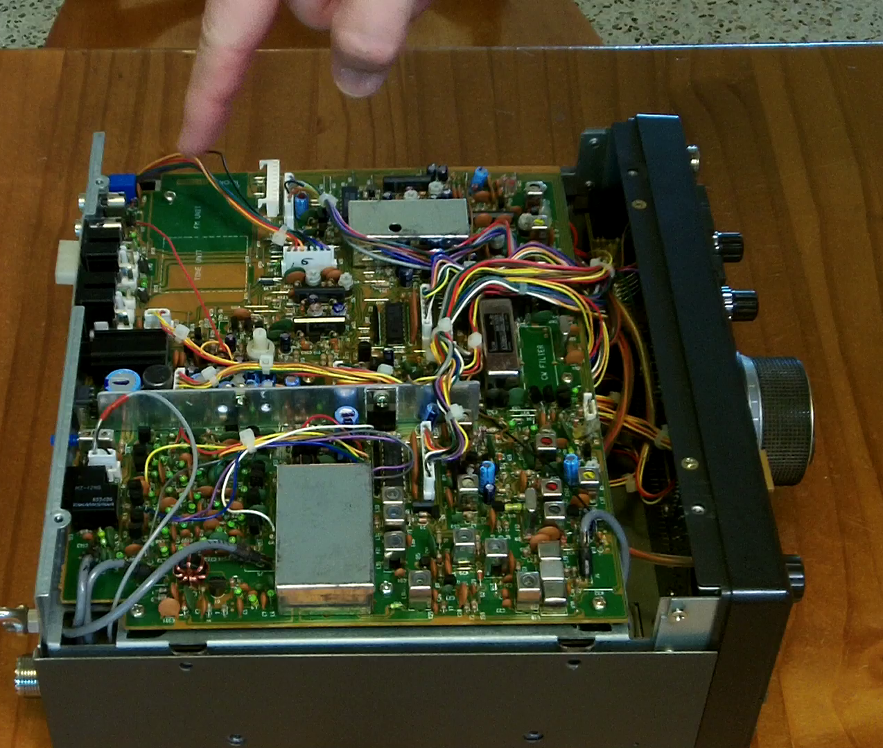
The FL-100 or FL-101 (500Hz or 250Hz) Narrow CW Filter units plug into the front middle of the bottom main board. You can faintly see a rectangle in white with the text “CW Filter” inside it on the green circuit board to the left of a silver crystal if the optional CW narrow filter is not installed. [If it IS installed, it will look like a larger rectangular prism that covers the “CW Filter” writing, usually silver in color with a black sticker on top.]
![]()
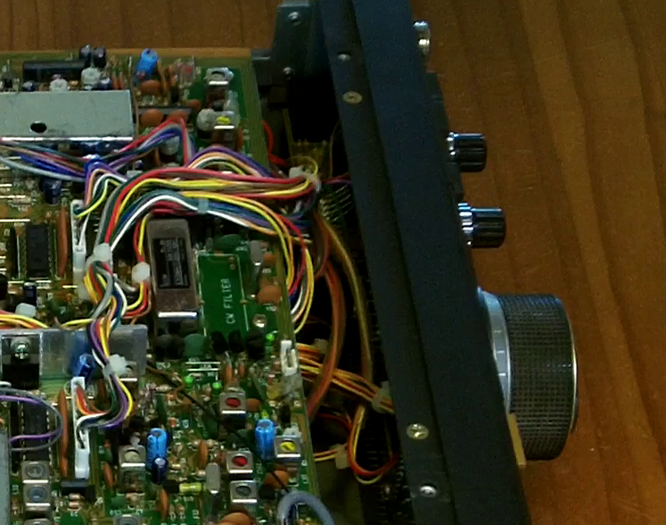
Empty location for the narrow CW filter outlined in white with “CW FILTER” on the main circuit board
The UT-30 Programmable Tone Generation unit plugs into the UI-7 unit but is invisible from the outside of the radio as it is sandwiched between the main board and the UI-7 board when installed.