Our old family car, a 1998 VW Passat (B5) is still running great, but having lots of problems with trim pieces and misc non-drivetrain parts. For example, if you lock the car and then unlock it, it would take 10-15 pulls on the passenger door handle (inside or outside) before the door would unlatch.
Category Archives: Projects
LED Headlight Upgrade – 1995 Chevy S-10
The low beam in one of my headlights burnt out, and since it’s a 4×6 sealed beam unit, I have to replace the whole thing. I decided to replace both the driver and passenger side at the same time so that they match, and upgrade to LED units by GENSSI (4×6 G3) that also add the ability to have always on daytime running lights (DRL). (As opposed to always driving around with my low beams on.)
The (1995-1997) Chevy S-10 only has two headlight units and the factory sealed beam headlights (H6545) use a weird plug shape that is not the standard H4 (the ground plug is twisted about 45 degrees). They are rated at 65 watts on the high beam and 45 watts on the low beam, but for nighttime driving I have never been happy with their light output.
The GENSSI (4×6 G3) that I am replacing them with has a measured power consumption for one unit at 14.4 volts on my bench power supply of 1.8 A for high beam, 1.03 A for low beam, and 0.08A (8ma) for the DRL. This works out to 26 watts, 15 watts, and 1.1 watt for a single unit. The eBay auction page claimed 25, 20 and 1.1 watts for high/low/DRL, so the measured figures mostly match the online specifications, giving me hope that the specified lumen ratings may also be somewhat correct (Claimed at 2150/1800/57 lumens).
These units cost me $40 each, compared to the $15 replacement cost for a direct drop in Wagner H6546. However, the cost didn’t stop there, as I needed to pay an extra $30 for two adapters from the OEM socket to the H4 plug on the LED headlights. I could have just cut off the OEM connector and wired in a H4 socket for less money, but I decided to pay for the adapters to make the installation plug and play as well as retain backwards compatibility. Supposedly LED lights should last practically forever, but if I ever need to replace them in a hurry I want the ability to go back to the OEM 4×6 units which can be picked up at most auto-part stores.
The difference between the LED’s and the original headlights is quite apparent, as the LED’s are a “cooler” color temperature (white, not yellow) and brighter, which is why I am changing out both headlight units even though only one burnt out.
Here you can see a comparison of the new LED on the left and the original halogen on the right, shining on a garage door in the day and at night.
I paid an $80 premium for the LED lights as opposed to the cheap OEM halogen replacements. For that $80 I get a cooler color temperature (for a more modern look), more light (better nighttime visibility), minor energy savings, and the ability to wire in true daytime running lights if I decide to make the effort (not yet connected).
Building a lofted storage shelf from a single sheet of plywood
My rental garage has 10+ foot ceilings, and I have a lot of stuff to store. To utilize the vertical space, I built a lofted storage shelf from fourteen 2×4 studs and a single 4×8 sheet of 3/4″ plywood to go over my electronics project table. This is what it looks like before I added the electronics table, pegboard and shelves.
Because I’m renting, I needed the unit to be free-standing, and not attached to the walls. I had the plywood ripped at 30″ at home depot for a 96″ wide and 30″ deep shelf, leaving me an 18″x96″ section that was used for both the back and side bracing panels.
Saving Space with an overhead shop vac
I have a 12 amp wall mounted shop vac, but I’m not allowed to screw into the walls of my rental garage. I also want to use it at the same time as other high power tools, like my table saw or drill press. This is a problem, because if the tool and the vacuum are both running on the same 15 amp circuit, the breaker trips. My rental garage has a single 15 amp circuit for all of the outlets. Except this one, which is on the same circuit as the lights.
I doubt I’ll be opening or closing the garage door at the same time as I run the shop vac, so putting the vacuum on the lighting circuit solves a lot of problems.
I bolted a 2×4 to the metal rail with 5/16″ screws and nuts and then mounted the vacuum to that.
My countsink bit was too small to fully fit the head of this 5/16 screw, so I drilled a 1/8″ pilot hole, then used my 5/8″ spade bit to drill a small impression before drilling with 1/4″ and 5/16″ bits and then using the countersink bit for the bottom of the conic section.
I needed somewhere for the hose, and the mount needed stabilizing along the Z axis so it doesn’t wobble when you turn the vacuum on or off, so I put another 2×4 on the other side for the hose mount and connected them together with deck screws for stability. I wired up a switched outlet that I can (just barely) reach from the ground, with an extra outlet in case I want to plug anything else into the secondary circuit.
Now I can run the vacuum at the same time as other high current shop equipment because they are on different circuits, and it’s off the floor and out of the way.
A video of the same content on YouTube:
Sink Drain Sizes
Repeat after me: 1-1/2″ for kitchen sinks, 1-1/4″ for bathroom sinks. Or, you could construct an adapter like this….
Follow along with me from left to right: we start with a 1-1/2″ to 1-1/4″ drain and trap connector, which is required to connect to the steel drain pipe. But then things go downhill, as we have a 1-1/4″ to 1-1/2″ adapter, a 1-1/2″ (kitchen sink) P-Trap, followed by a 1 1/2″ to 1 1/4″ adapter to connect to the bathroom sink drain.
I’d like to think that somebody decided they really wanted a larger P-Trap on the master bath sink…but I suspect that the plumber only had a kitchen sink P-Trap in his truck and didn’t want to make a special trip
Since I needed to change the length I went ahead and used 1-1/4″ throughout. I think it looks a bit nicer. (I also sealed the hole into the wall with expanding foam while I was under the sink.)
Secret birdhouse camera
This ratty old birdhouse has a secret. It was actually an “outdoor enclosure” for an indoor WiFi security camera (D-Link DCS-920). The birdhouse worked well over the last five years protecting the camera from the weather. (I lost one power supply, which hangs outside the birdhouse, so I waterproofed the replacement with hot glue and lots of layers of electrical tape.)

It looked better five years ago (the perch was gnawed off, probably by a squirrel), but it was never operable as a birdhouse, as the entry hole is covered by clear Plexiglas and acts as the viewport for the camera. It’s basically the opposite of Dennis Nino Clasen’s birdhouse camera:
Now that I’m retiring it, I can post the secret on the internet. It was relatively difficult to notice the camera inside the birdhouse. Over five years of operation, I only know of one person who noticed that it was a camera (and then called over the whole crew to take a look…)
I did feel (only slightly) guilty about the number of birds that flew to the perch and tried to go inside….
One of these animals is not the same….
Cooling Ducts – Mostly successful for charging at 30 Amps
Adding cooling ducts to my chargers was mostly successful. I am still able to make the chargers overheat (and shutdown) when charging in hot 95-100 °F outdoor temperatures at the maximum 30 A rate, but it takes them longer to do so. I can work around this by charging at a lower rate or delaying charging until the day is cooler. I have my “80%” charging profile set to use the recommended 25A rate instead (and may even lower this depending upon the results of future temperature logging sessions).
However, on rare occasions I may need to charge as fast as possible for one to two hours at a charger away from home (to extend my range). I would typically not be making long trips in 100 °F temperatures, so I tested charging at the full 30A rate on an 80°F ambient day, which generated the following graph. (I have two chargers, so they each have their own watts and temperature line.)
Inexpensive cooling ducts with hardware store parts for my dual chargers
In an effort to counteract overheating, I have added cool air intakes connected via 4″ diameter ducts to the fans on my TSM2500 (CH4100) chargers.
I used a 4″ flush to the floor “snap-in” PVC floor drain (designed to be cemented inside of a 4″ PVC pipe) spray painted flat black as my intake, connected to a 4″ aluminum flex dryer hose (mostly ran straight through, but the flex hose allowed me to vary the length) with worm screw clamps (a.k.a. hose clamps). The single most expensive part of the install was the 4″ hole saw ($15 on ebay, or $20 at the store). I could have saved $5 by going with a less expensive vinyl dryer hose, but I like the rigidity and appearance of the aluminum.
TSM2500 (CH4100) Chargers Overheating
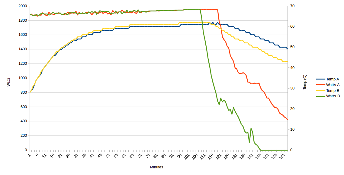
Now that it is summer, and outside temperatures are reaching 26-35 C (80-95 F), my dual TSM2500 (Rebranded CH4100) chargers are overheating. After about an hour charging at full power, they reach around 74 C (165 F) and shut down. The ThunderStruck Motors EVCC records this as a “normal” end charging event (because the Amperage output goes to zero), and for some reason it triggers a ground fault on my EVSE (perhaps they have a thermal switch that shorts the charger to ground to shut it down, or maybe my JuiceBox Pro 40 is just overly sensitive?)
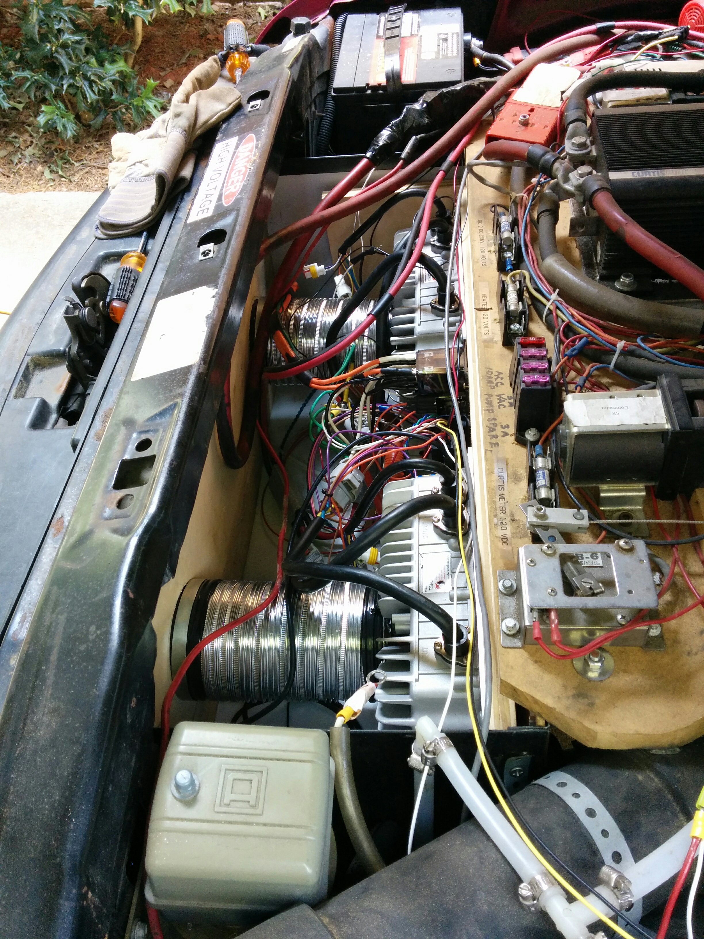
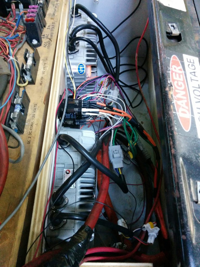
I guess the overheating is to be expected, as the chargers are in a five sided box (with only the top open) and mounted to a piece of (thermally insulating) plywood. Although there is a tangle of wires in front of them, the wires really don’t interfere with the airflow as much as it looks like from this top view.
In my defense, the charger’s manual (v. 1.05) specified that I should leave a 50mm (2in) gap in front of the charger for proper ventilation and I left around 8 inches. It also noted that the “Working temperature” for the chargers was -25 to 55 C (-13 to 131 F). It didn’t mention anything about thermally bonding the charger to a heatsync.
As a temporary solution, I have re-configured my 80% charging profile to only run at 1.2 kW (8 amps total, or 4 amps per charger on a 128-131 volt pack). This is about 25% of the 15 amp max power that the chargers are capable of in cold weather. At this relatively low power, each charger is outputting just over 500 watts, and even in 32 C (90 F) weather the charger temperature hold steady at 50 C (122 F).
Charging at one kW may not sound terribly fast (it’s not), but this workaround is actually fine for 95% of my charging needs, as I rarely need to refill more than 8-10 kWh (20-30 miles) per day of use, and L1 charging overnight works fine for most of my needs.
However, I purchased the dual charger setup so that if I was necessity charging away from home I could charge at a 4 kW rate, so I want to make improvements to my cooling so that I can run the chargers at full power (without them overheating after an hour) if needed.
ThunderStruck Motors suggested that I mount the chargers to an aluminum heatsync, which is a good idea, but difficult and costly to implement.
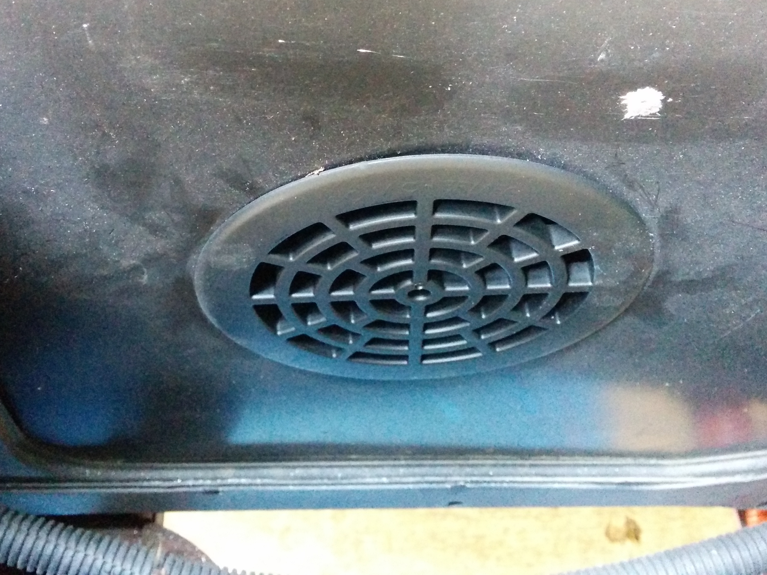
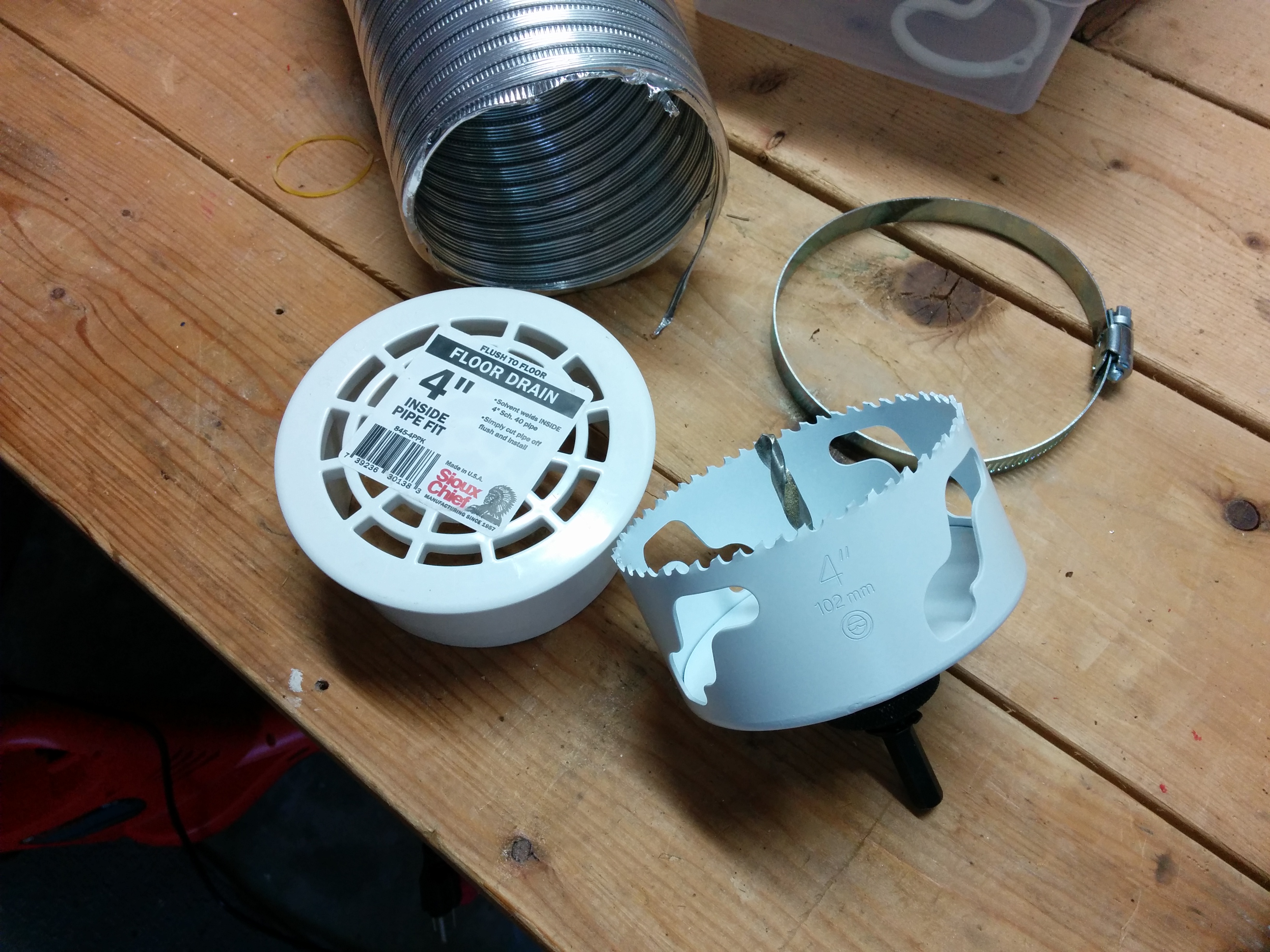
I have decided my first order of business is to drill two 4″ air intake holes into the bottom of my charging enclosure and duct them to the top of the chargers right over the fan using dryer hose. This will allow the fans to draw cool(er) outside air directly over the vanes on the charger, and keep the heated exhaust air from mixing with the cool(er) incoming air. Since the top of the box is open, the heated output air should have no problems escaping, as convection will assist the fans in exhausting the hot air upwards. If adding intake air vents doesn’t solve my problem, then I’ll worry about making an alunimum heatsync plate to take the place of the plywood.
Lathe Break Out Board mounting
Here is a picture of the final wiring layout of my Lathe after installing the parallel port break out board (top left). I made use of the built in wiring trays to organize all of my wires that plug into the 96 way header on the NextMove ST stepper controller board.
Here is a closeup of the break out board and it’s acrylic mounting plate.


