In the month of May, the ring app cost me $40 (I pay $10 a GB for cellular data).
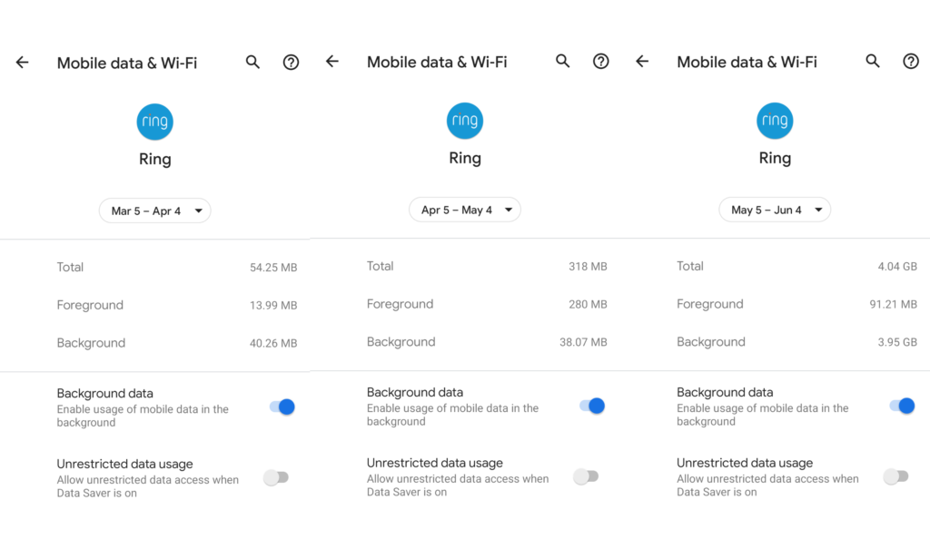
Having the ability to see what is going on around the house when I am away is worth spending some mobile data on…in March it cost me 54MB, and in April it cost me 318 MB (54 cents and $3.18 cents respectively). However, that is FOREGROUND data, that is actively used when I am streaming data in the app. Sometime after May 5th, the ring app started to download a LOT of background data. In fact, for the May5-June 4th month, I used 91 MB of foreground data, and the ring app used 3.95 GB of background data (that’s $39.50 it cost me).
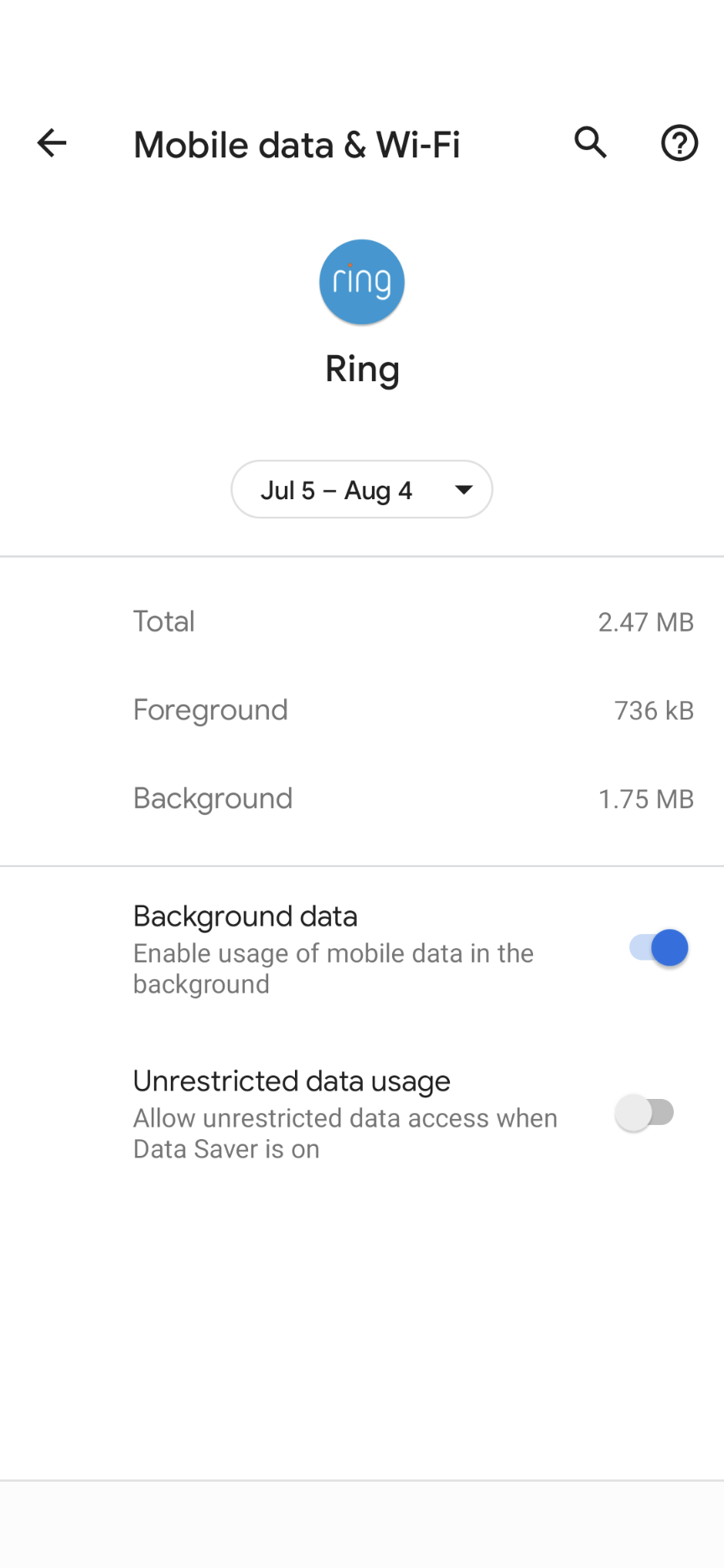
[Soon after taking these screenshots, I disabled “Background data” for the ring app, which prevented it from using more excessive amounts of (cellular) data and costing me money.
My current version of the ring app is 3.40.0, running on Android 11 on a Pixel 4A phone.
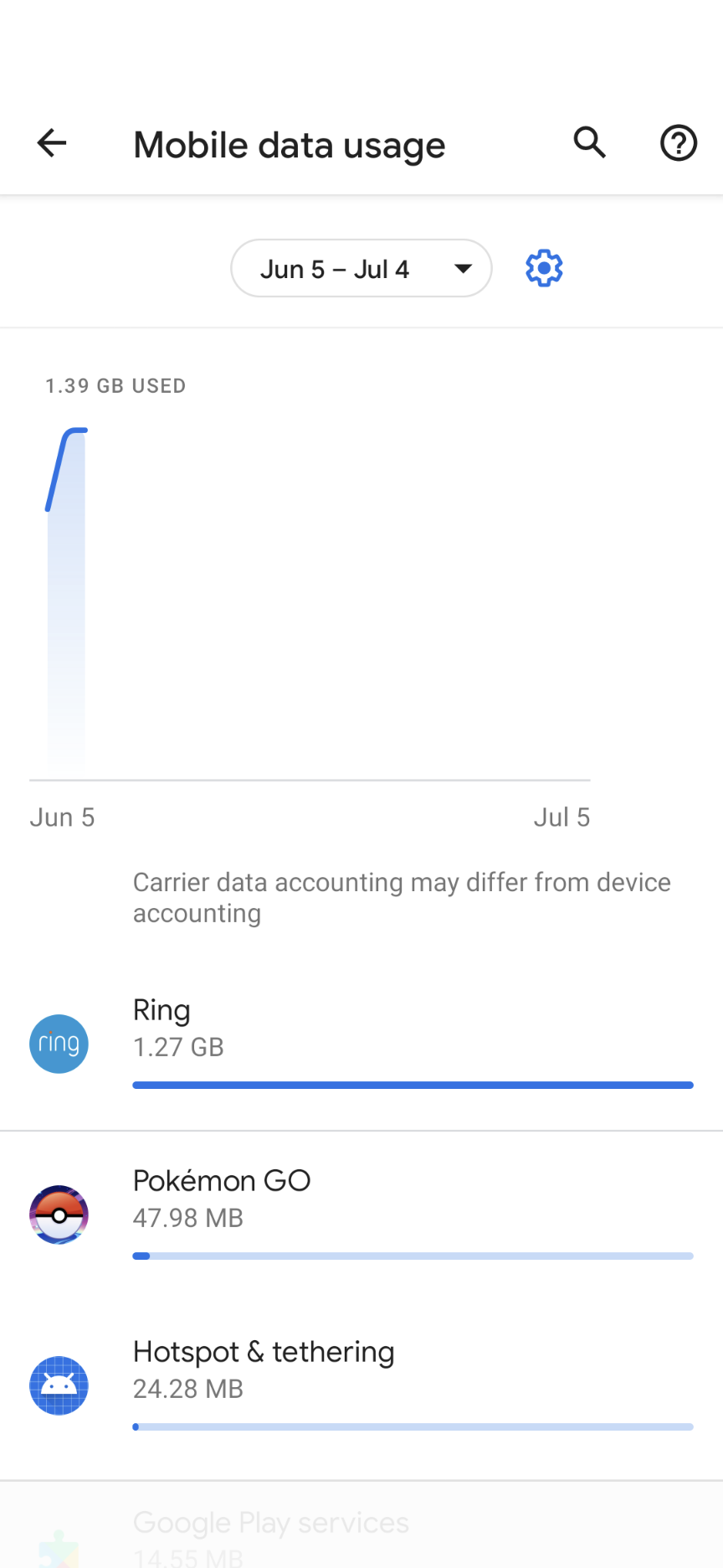
After I got the $40 larger than I was expecting bill in June, I quickly checked to see what was using all of that data, and found that the Ring app had used 1.27 GB of data in only a few days. To put that in perspective, it was using more data than Pokemon GO, which is usually my highest data using application.

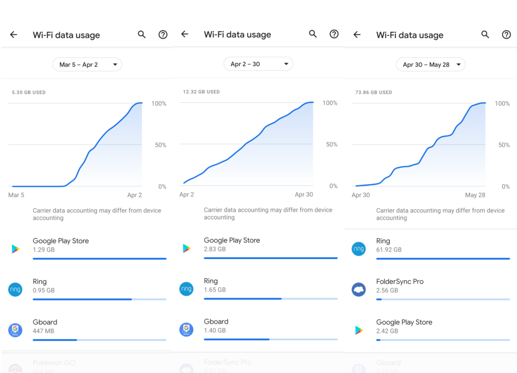
The problem is not limited to cellular data, the ring app has become a massive data hog when on wifi as well (but at least since my wifi connection is not metered, it doesn’t cost me anything). Every so often when I am at home I will use the ring app to watch the video feed from a camera if I get a motion alert and don’t want to get up to look out the window. In March and April this usage amounted to around 1 GB and 1.7 GB of wifi data respectively. But, in May, the ring app used 61 GB of wifi data!
I did not stream more video in May than in previous months, so this is primarily background data usage by the app.
If I had to guess, I suspect that the ring app on android has started automatically downloading videos of motion that occur, EVEN IF THE USER DOES NOT WATCH IT! Perhaps this a feature designed to make the app more responsive if the user selects the notification to view the video stream, but when I talked with technical support, they could not offer any explanation for why this was happening or how to disable the high data usage.
Update – Ring app 3.41.0 appears to have fixed the issue
After the Ring app upgraded to version 3.41.0 on Android, I re-enabled background data and kept a close eye on it for a few days. Including a few times I was away from wifi on cellular data, the data usage was much more reasonable, so it appears that the ring developers have fixed whatever the issue was.