Salvage 2013 Nissan Leaf modules – 7 year old range update

Back in January of 2016 I put a set of battery modules harvested from a salvage 2013 Nissan Leaf into my S-10 conversion electric pickup. In march of 2016 I drove the truck for a while to see what its range was. [More than 46 miles, as I got tried of driving. The pack had a capacity of at least 15 kWh at that point in time.]

37.4 miles on trip meter.

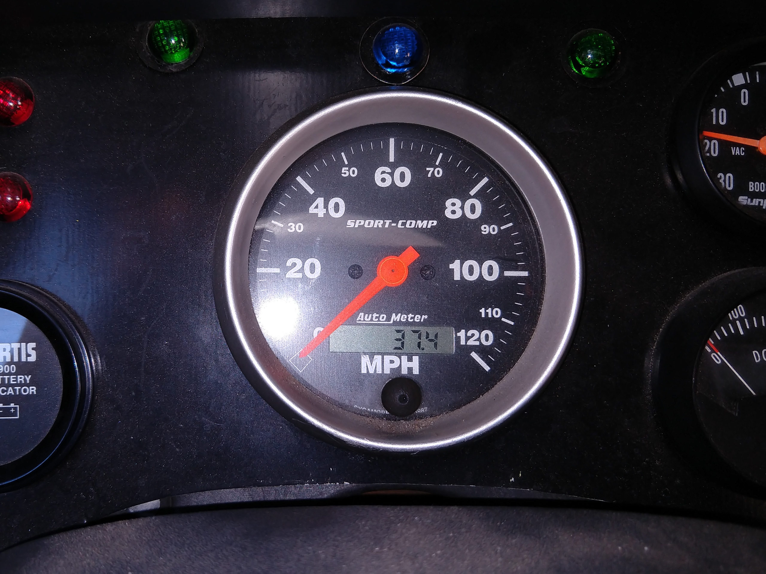
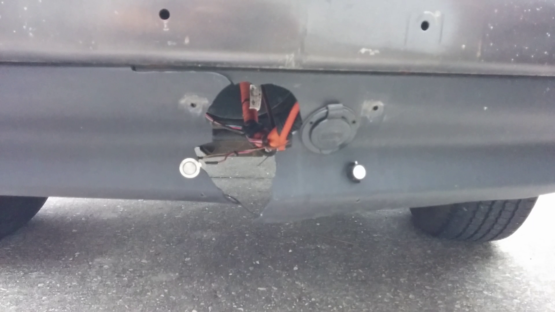
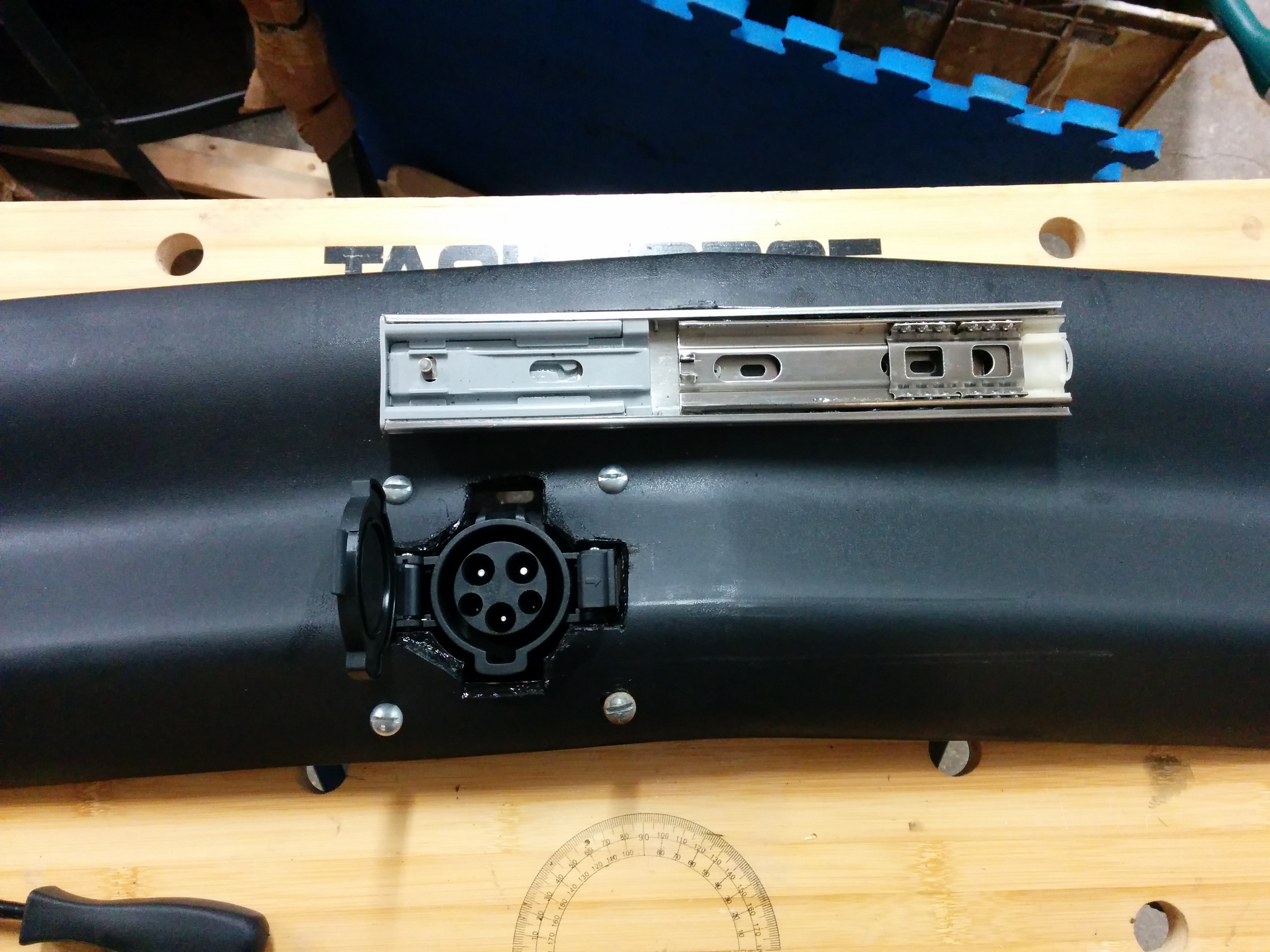
Today I drove the truck for 35.8 miles before the low cell warning beeper from the BMS started to alert. After I got home [37.4 miles total], the average cell voltage of the pack was 3.75, while my (one) lowest cell was down at 3.3 volts. As it turned out, that cell must have started the trip out at a lower state of charge / voltage from the other cells, as it was still low when charging finished and I had to manually add charge to it individually. [My BMS does a good job of alerting at high/low voltage conditions, but does not do much for balancing the pack.]

According to my JuiceBox, the pack required 14.74 kWh to recharge, which is a good estimate on the battery pack’s current capacity. [This is almost exactly the same amount of power that I used in the trip in 2016, but I didn’t go as far due to different driving conditions. And I also hit the bottom of (at least one cell’s) state of charge.

The 2016 trip averaged 322 watt-hr/mile. This trip consisted of a lot of stop & go city driving as well as a few lengthier stretches of 49 mph arterial streets, and I wasn’t light on the accelerator. My measured watt-hour / mile (from the wall, including charger losses) was: 394 watt-hr/mile

Assuming that the pack has a 15 kWh capacity, this is 63% of the brand new 24 kWh capacity, which means I lost 37 % of the capacity over 7 years. (Some of that was in the original Nissan Leaf, but most of it was in my s-10 conversion.)

I’ll repeat the test after balancing my cells a bit better and see how things go.

Update: I drove the truck until the low cell beeper came on again. I went a total of 38.5 miles, and recharged the pack with 16.69 kWh (16690 watt-hours). The relatively higher   433 watt/hours per mile number is a result of the weather being a lot cooler so I was running the heater in the truck and more 45 mph roads. Balancing the cells got the usable pack capacity (measured from the wall with charging inefficiencies) to 16.69 kWh (which could have theoretically gotten me to 42 miles at 394 watt-hour/mi or 51 miles at 322 watt-hr/mile)

The main take-away is that at 16.5 kWh, I still have access to 68% of the brand new 24 kWh capacity Leaf pack, which isn’t too shabby for a 7 year old battery.


New charging inlet & Drive Away Protection


So, this happened. A year and a half of meaning to get around to installing the drive away protection circuit later, I eventually drove away while the J1772 charger was plugged in, which yanked my inlet out of the truck, breaking the plastic air dam in the process. (Luckily, my EVSE wasn’t damaged.)   $150 later, I had a new J1772 inlet and air dam, and had to re-do all of my mounting work. I took this opportunity to re-work how the license plate mounted. Instead of tipping up (which shielded the inlet from view and made it hard to plug in without kneeling) I decided to make it slide to the side so that it would be easier to see and plug into the inlet. I used a 12″ stainless steel drawer slide (with self/soft closing features to keep it closed) for the motion.

Mounting the 15 amp RV inlet, button, and rotary switch was a simple matter of drilling the appropriately sized holes, but the J1772 inlet needed a custom mounting block that would match the interior contour of the air dam so that it could be recessed behind the license plate.

I assembled a stack of laser cut plywood into a block with the correct bolt pattern and cutout for the J1772 inlet, and then I sanded it down to match the interior contour of the air dam. I painted it black and mounted it to the inside of the air dam, and then screwed the inlet to the back of the block.

I also hooked up my drive away protection circuit. Here is a video of the finished system in operation.

Curtis 1231c upgrade: Binning Gate Drive Resistors

I am upgrading the power board of my Curtis 1231c DC PWM motor controller. It uses 18 MOSFETs to switch the power, and each MOSFET had a 47 ohm resistor on it’s gate input. The point of such a high resistance was to slow down the switching of the MOSFET’s so that they would all share the current somewhat equally and no single MOSFET would turn completely on before all of the others had a chance to start shouldering the load.

Continue reading

Curtis 1231c Power Board desoldering

I desoldered all of the main power components (diodes, MOSFETS, capacitors) from the power board of my failed Curtis 1231c PWM DC motor controller. The plan is to upgrade all of the components to give it higher capacity; while producing less heat. Of course, to replace them, I had to remove the old ones, which took around 6 hours of work with two different soldering irons and a solder sucker.

My advice:
-Heat component legs (diodes/MOSFETS) from the top of the board (side with the component) while you solder-suck from the bottom. Get one leg completely free first, then work on the other. After you suck almost all the solder out, you may still need to re-heat the leg and push it away from the PCB with a small screwdriver so it doesn’t stick to the inside of the hole.
-For the capacitors, don’t be afraid to add a little solder to the smaller leg, and then use a 100 Watt super wide tip soldering iron to heat both legs up at the same time, and pull the capacitor straight out. Suck the solder from each hole individually later once all the components are gone.
-I heartily recommend the Engineers SS-02 Solder Sucker, the silicon tube it uses is great! I did get solder stuck inside the metal tip a few times, but nothing a 5/64th drill couldn’t fix right up.
Continue reading

Curtis 1231c diodes: Diotec DR7506FR vs TSR2402R

I am looking to replace the MOSFETS, diodes, and capacitors in my Curtis 1231c with upgraded components. I unsoldered one of the existing TSR2402R (7103 K) diodes from the power board and tested it with my Fluke meter and bench power supply.

Here are my results:
Power Supply providing 3.2A, forward voltage drop: 0.776 volts
Power Supply providing 2.0A, forward voltage drop: 0.737 volts
Power Supply providing 1.0A, forward voltage drop: 0.697 volts
Fluke Diode Setting: 0.351 vdc

Average time for the button temperature to raise from 25 °C to 50 °C with a 3.2A current: 45 seconds

The replacement parts I purchased were from DIOTEC, specifically their DR7506FR model (the R at the end means “Reverse Polarity”, making them an exact drop in replacement in form factor and polarity). They were marked: “DT110   DR7506FR” plus a diode schematic. Here are my results for the upgraded component:

Power Supply providing 3.2A, forward voltage drop: 0.754 volts
Power Supply providing 2.0A, forward voltage drop: 0.700 volts
Power Supply providing 1.0A, forward voltage drop: 0.646 volts
Fluke Diode Setting: 0.399 vdc

Average time for the button temperature to raise from 25 °C to 50°C with a 3.2A current: 47.5 seconds

Of course, the original diode I’m measuring had been in use for many years (I estimate ~750 hours of driving time given the 22K miles) and was heated up as part of the soldering and unsoldering process, while the DR7506FR I tested was brand new straight from the manufacturer. After I unsolder a few more diodes I’ll check them to make sure their readings are similar. (I’ll probably also test a few other DR7506FR diodes from the bag as well.)

Of all the measurements, the temperature rise time measurement was the least scientific, as I was using an inexpensive non-contact IR thermometer and attempting to point it at a small button in each diode, waving it back and forth to find the hottest temperature. I took 4 measurements on each diode (alternating to let the other one cool down) and averaged them together. In general, the readings from the DR7506FR were longer than from the original TSR2402R with one exception. If I throw out that pair of readings, the averages would be 46 seconds vs 50 seconds. Given that the measured forward voltage drop for the DR7506FR was lower for any real amperage readings, it dissipating less power and taking longer to rise to 50 °C appears to be reasonable.

Curtis 1231c Replacement Power board components

My Curtis 1231C motor controller blew up some MOSFETs and died. I replaced it with a used unit to get my truck back on the road, but now I’m interested in repairing the one that died so that I’ll have a spare.

I might be able to replace the components that died with exact replacement parts (but the IXTH50N20 MOSFETs are hard to find nowadays, and the diodes are basically unobtainable) to get it working, but since I have it open and am doing all of this work, I am exploring alternative (new) components that will have higher ratings and possibly give my controller more capacity or at least more resistance to blowing up again.

Of course, if I replace one component (power switching MOSFET, freewheeling diode, or ripple controlling capacitors), I will probably need to upgrade the other two as well so that I don’t just move the weak link from the MOSFETS to the capacitors or diodes.

Continue reading

Curtis 1231C-8601 500A PWM DC Motor Controller teardown

After replacing the Curtis 1231C-8601 motor controller that had failed, I opened the case up to figure out what had failed.   The controller hardware is inside of an aluminum extrusion with both ends “potted” with some black semi-flexible material (hard silicon perhaps?) that could be cut using a razor knife and a lot of effort.


Inside, there is a Pi shaped piece of aluminum extrusion that acts as the heatsink for the MOSFETS and freewheeling diodes, as well as being electrically connected to the motor – terminal. It is held against a large thermally conductive, but electrically insulating pad, which separates it from the controller case, but allows heat to be dissipated. It is held in place with 8 screws that pass through insulating plastic brackets into the bottom of the case.

People online had told me that these screw holes were “potted”, but on my controller they were just filled with two rubber plugs.They also told me that you could not cut through the Curtis potting material with a razor knife. [This super hard potting material was also prone to cracking at the edges and letting moisture into the controller, so a flexible rubber like material is better anyways…]

Continue reading

LED Headlight Upgrade – 1995 Chevy S-10

The low beam in one of my headlights burnt out, and since it’s a 4×6 sealed beam unit, I have to replace the whole thing. I decided to replace both the driver and passenger side at the same time so that they match, and upgrade to LED units by GENSSI (4×6 G3) that also add the ability to have always on daytime running lights (DRL). (As opposed to always driving around with my low beams on.)

newledheadlight

The (1995-1997) Chevy S-10 only has two headlight units and the factory sealed beam headlights (H6545) use a weird plug shape that is not the standard H4 (the ground plug is twisted about 45 degrees). They are rated at 65 watts on the high beam and 45 watts on the low beam, but for nighttime driving I have never been happy with their light output.

original_hp6545 95-97-chevy-s-10-headlight-plug


The GENSSI (4×6 G3) that I am replacing them with has a measured power consumption for one unit at 14.4 volts on my bench power supply of 1.8 A for high beam, 1.03 A for low beam, and 0.08A (8ma) for the DRL.   This works out to 26 watts, 15 watts, and 1.1 watt for a single unit. The eBay auction page claimed 25, 20 and 1.1 watts for high/low/DRL, so the measured figures mostly match the online specifications, giving me hope that the specified lumen ratings may also be somewhat correct (Claimed at 2150/1800/57 lumens).

These units cost me $40 each, compared to the   $15 replacement cost for a direct drop in Wagner H6546.   However, the cost didn’t stop there, as I needed to pay an extra $30 for two adapters from the OEM socket to the H4 plug on the LED headlights. I could have just cut off the OEM connector and wired in a H4 socket for less money, but I decided to pay for the adapters to make the installation plug and play as well as retain backwards compatibility. Supposedly LED lights should last practically forever, but if I ever need to replace them in a hurry I want the ability to go back to the OEM 4×6 units which can be picked up at most auto-part stores.

The difference between the LED’s and the original headlights is quite apparent, as the LED’s are a “cooler”   color temperature (white, not yellow) and brighter, which is why I am changing out both headlight units even though only one burnt out.

Here you can see a comparison of the new LED on the left and the original halogen on the right, shining on a garage door in the day and at night.

new_vs_old_daylight

new_vs_old

I paid an $80 premium for the LED lights as opposed to the cheap OEM halogen replacements. For that $80 I get a cooler color temperature (for a more modern look), more light (better nighttime visibility), minor energy savings,   and the ability to wire in true daytime running lights if I decide to make the effort (not yet connected).