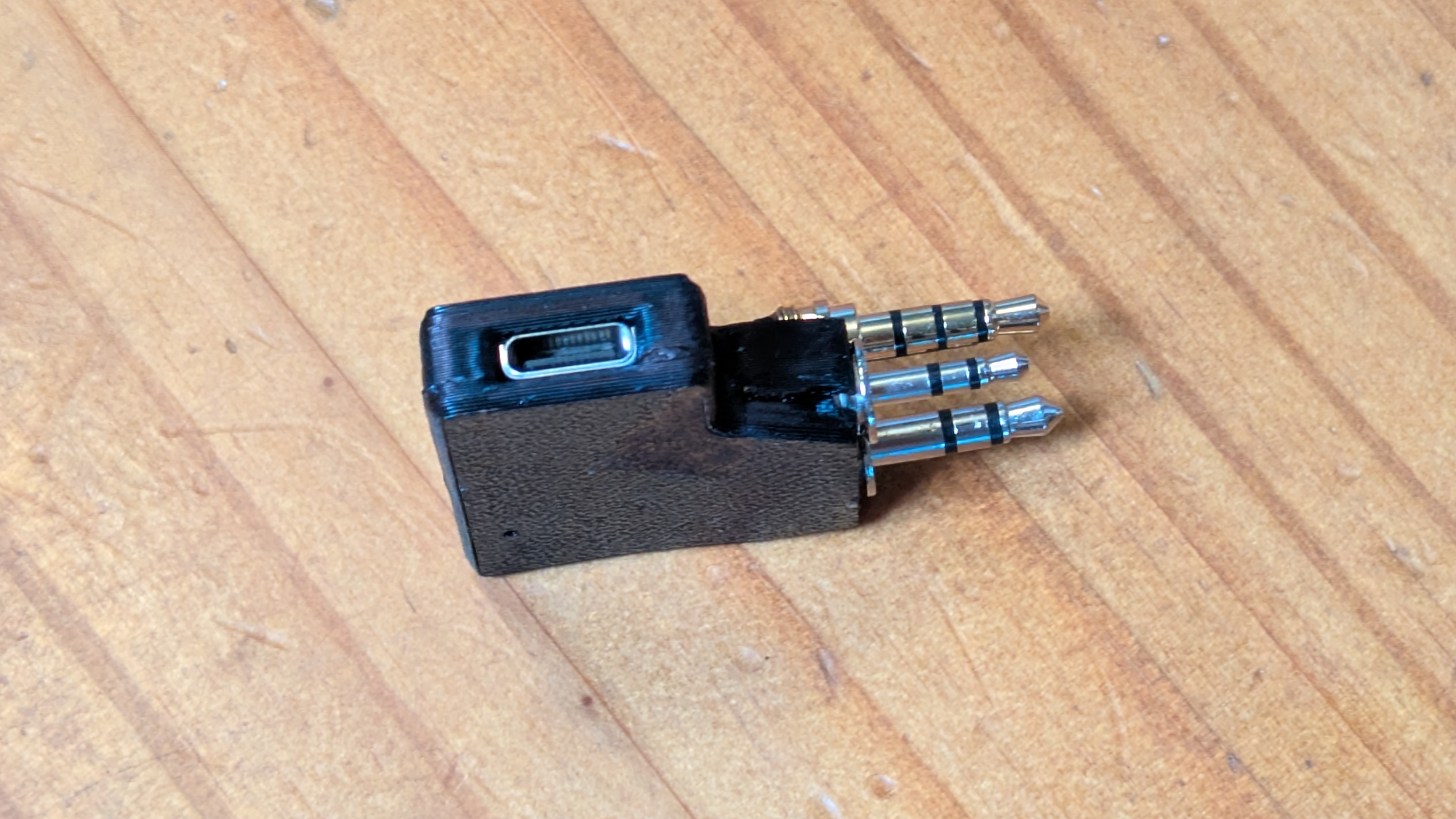
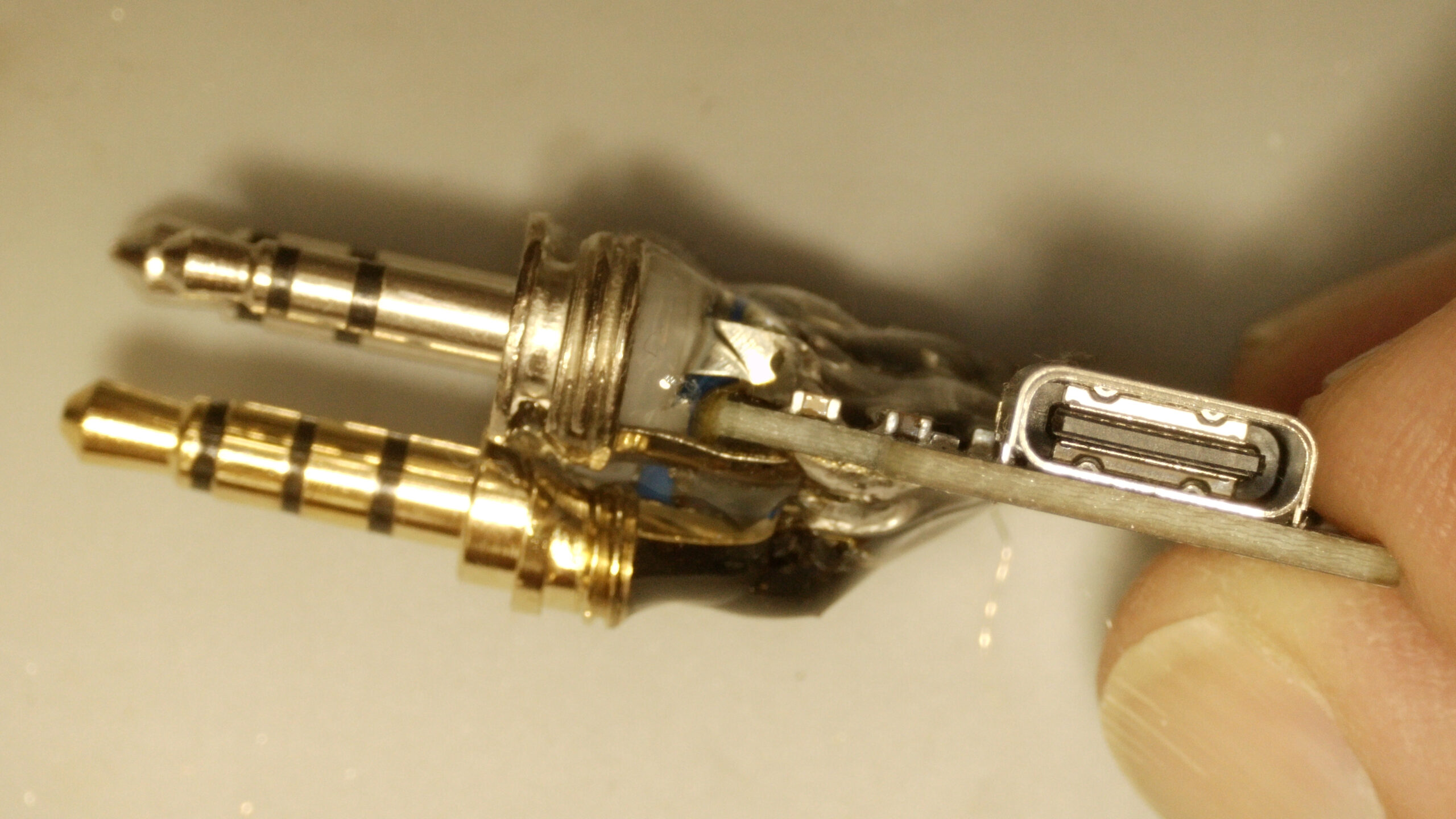
I added a 3rd 3.5mm plug to the open hardware AIOC sold by NA6D to send the serial data to the CAT port on my uSDX+ SDR radio.
I added a 3rd 3.5mm plug to the open hardware AIOC sold by NA6D to send the serial data to the CAT port on my uSDX+ SDR radio.
The iCom IC-725 Transceiver receives CW (Morse Code) natively, but you can install an optional “narrow” CW filter that gives you greater sensitivity / out of band rejection.
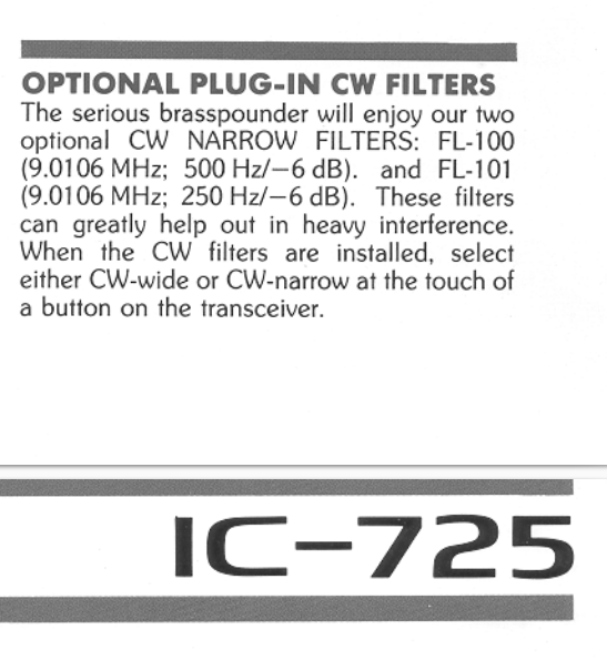
The FL-100 (500Hz notch) or FL-101 (250 Hz notch) are suggested in the IC-725 manual. I instead installed a FL-232 (350Hz) filter which is designed for later ICOM radios, but has the same form factor, and is designed for the same 9.01 Mhz IF that the IC-725 uses. This is a “happy medium” between the 500 and 250 sizes (Plus, I found a FL-232 for sale at $87 shipped, while most of the FL-100 and FL-101’s I’ve seen for sale are $120-150 shipped from Japan.)
My forward power meter was not moving at all, and it later turned out that the reverse meter wasn’t moving correctly. The root cause was that both of the diodes in the meter circuit had blown (Not sure why, perhaps somebody put a LOT of watts through the unit? Apparently this is a common cause of problems for the meters on MFJ tuners from this era).
The final solution was to replace both diodes (the forward diode had failed open, and the reverse diode had failed “closed” but not working as a diode properly so some forward current was going through it to mess up the reflected power reading).
These 1N34A Germanium diodes appear to work as well as the OEM diodes, even though they are not the blue/black color scheme and are physically smaller.
I didn’t want to unsolder all of the PL259 coax jacks and take the front cover & knobs off just to get access to the trace side of the circuit board, so I instead soldered the new diodes to the legs of the old diodes (so the old diode body would keep the legs from falling down if the solder on the traces below melted) and then clipped out the old diodes. Not as clean as if I had access to the bottom of the circuit board, but a lot faster and much less likely to break the set screw threading of the 30+ year old plastic knobs.
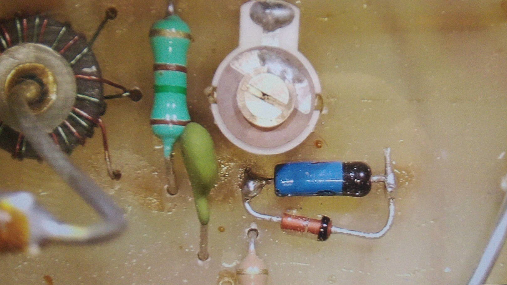
In the above image you can see one of the new diodes bypassing the old diode (before I cut away the original shorted diode). You can also see the “balance” tuning capacitor just above it, and the current sensing transformer with the transmitter feed-line going through the center at the far left.
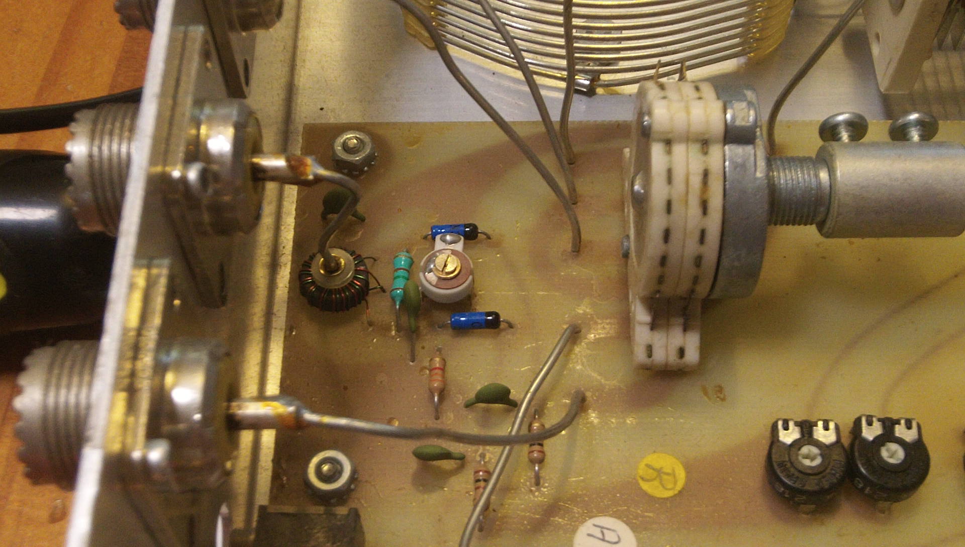
Two of the three 12volt incandescent “grain of wheat” light bulbs in my 30 year old iCom IC-725 radio had burnt out, making it difficult to see the meter at night. (And one side of my LCD was much dimmer than the other, although it was still readable.)
Although they are soldered to the front panel circuit board, replacing them is relatively easy if you have a fine tip soldering iron and good magnifying glasses.
Access requires you remove the top and bottom covers, and then unscrew the screws holding the front cover in place (two on each side, and two on the top in the silver metal, not the two holding the plastic panel in place). This allows you to “fold” the front cover down without unplugging any wires to get just enough access to solder from the back of the circuit board.
Here is a photo of the rear of the circuit board with the locations of the three lights marked in yellow (the red dot is a 4th hole that is directly behind the LCD, and looks the same, but was unpopulated in my radio. It’s possible a light is supposed to go there in the original design, but it doesn’t look like there is any way for the light to get to the back of the LCD panel from that hole (i.e. no light guides as seen in the other two holes on the sides of the LCD).
![]()
I just held each leg of the bulbs with a pair of tweezers and pulled it out of the solder blob after heating it up with my micro tip soldering iron. To install the new bulbs, I carefully clipped the legs to length, and then pressed them into the solder blob with the tweezers. [Only in one case did I have to add a drop of my own solder to help thermal conductivity to get the original solder to melt and flow around the bulb leg.] Be careful to not drop any metallic leg clippings into your radio.
The original bulbs were very small incandescent bulbs surrounded by a yellow overlay that makes them look like LED’s, but they are NOT LED’s. If you could find some 12 volt side throwing LED lights you could use those to replace them for longer lifespan, but given that the radio is 30 years old now and only 2 of the 3 original lights burnt out, I’m hoping these replacements will last a long time.
The ones I purchased were larger than the original lights, but fit the holes fine. I got them from e-bay seller: “Affinity For Artifacts” (About $12 shipped)
Qty 5 Light Bulbs Icom IC-720 IC-721 IC-725 IC-730 IC-735 S Meter Backlight Lamp
https://www.ebay.com/itm/126120391794
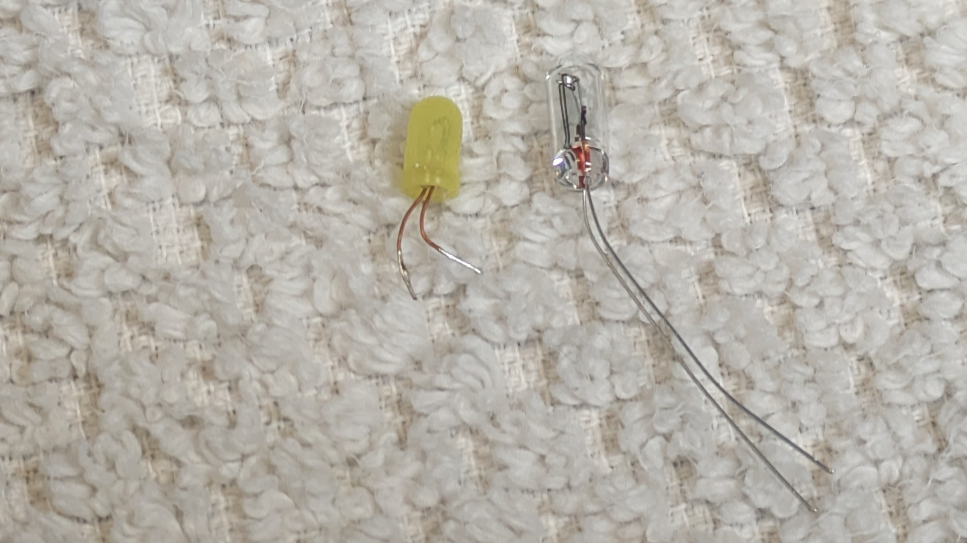
The original (yellow plastic cover) is on the left and measures:
3.35mm diameter, 6.25 mm length (plus wire leg length)
The replacements (on the right) measure: 3.74mm diameter, 10.15 mm length
(and stick out the back of the circuit board just slightly)
This photo makes the center of the LCD look darker than by eye (perhaps that mystery empty 4th hole was designed to counteract this?) but in person I didn’t find it very noticeable.
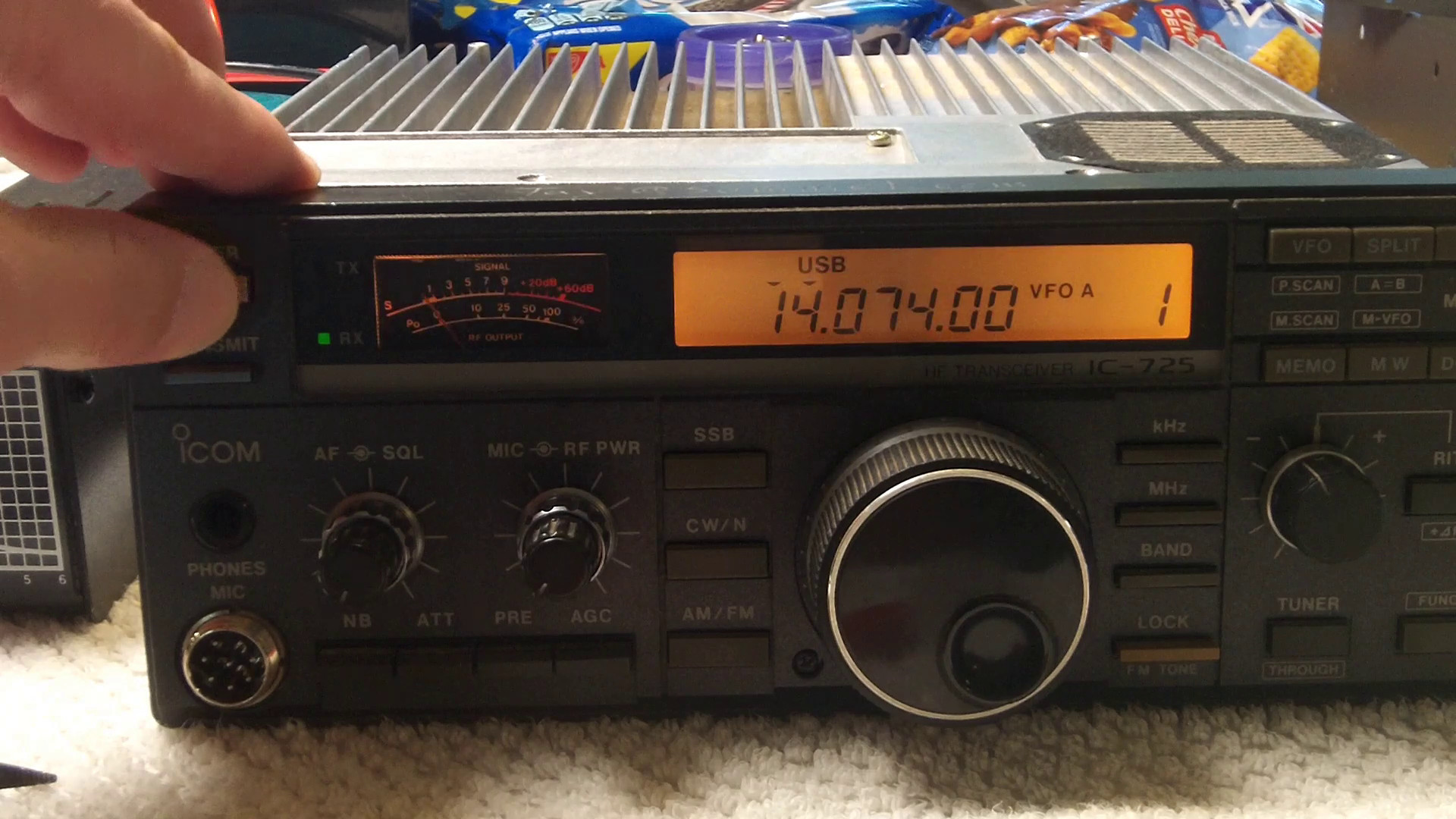
Final result
The 25 year old GPS module in my LX200GPS telescope has great difficulty getting a GPS fix. (My telescope is on a wedge, so the antenna is facing north instead of “up”, plus the backup battery died and is extremely difficult to replace without removing the telescope from the wedge. The biggest reason is that it is 25 years old.)
So I bought a modern BN-280 GPS module ($25) and a $10 USB->Serial TTL programmer, and replaced it. There are some technical details you need to get right to make it work (4800 baud, sending only $GPRMC messages, getting the wires hooked up right) but the overall process is relatively straightforward. Above is my howto video, and below is my big text dump:
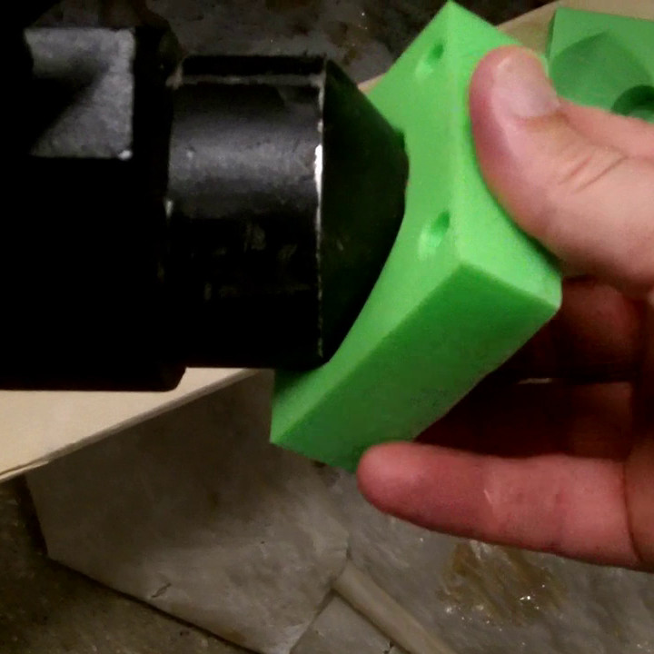
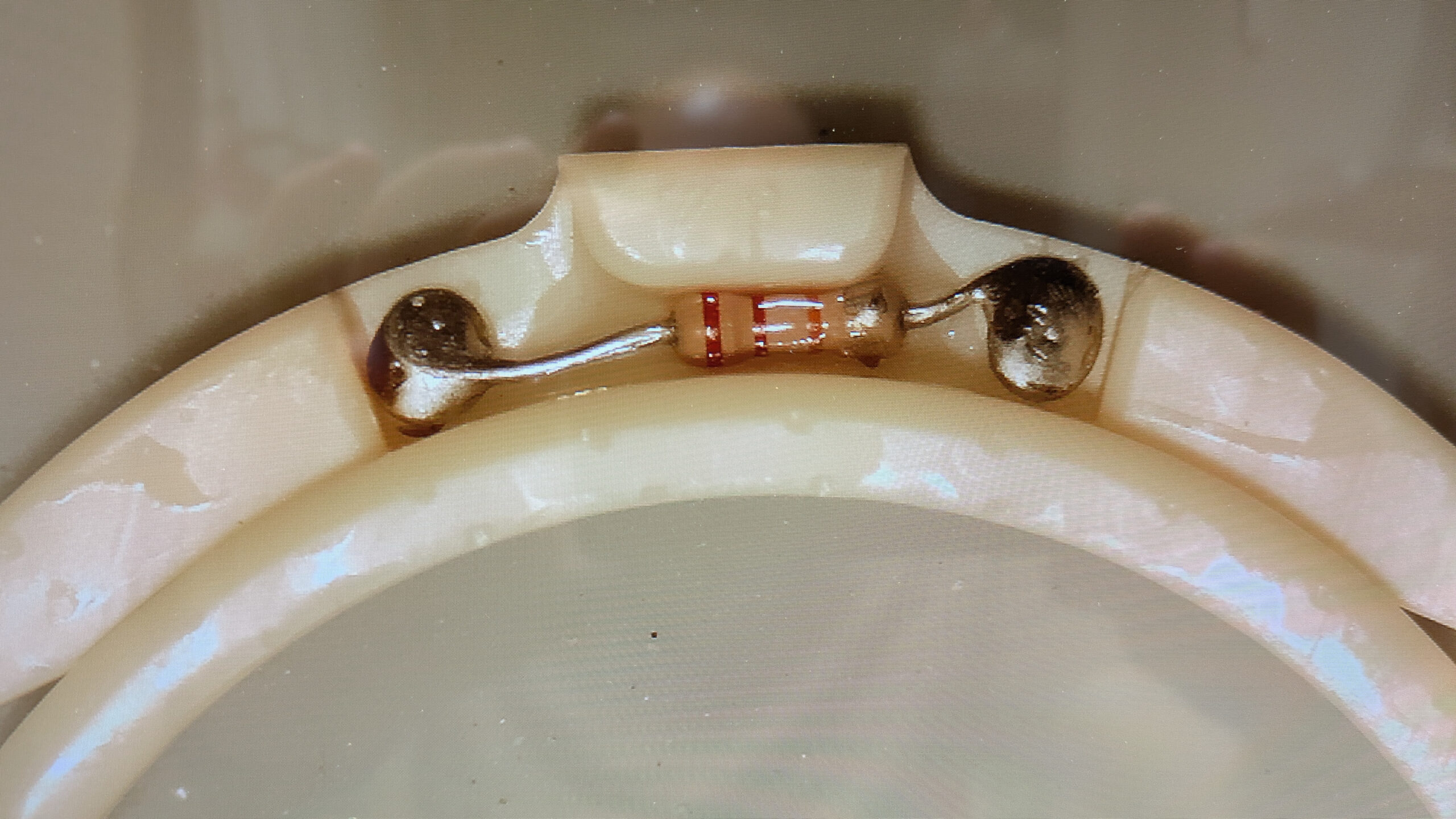
After my success with a Dual Band filter holder, I spent $38 on a sheet of BAADAR AstroSolar Safety Film (from ScopeStuff in Round Rock TX) and used some 3M VHB double sided tape (cut in very thin strips) to attach it to the 3D printed filter holder. The filter holder is really designed for screwing in a 2″ (50.8mm) astro filter, so it didn’t have as much surface area on the “ring” as I would have liked, but it worked reasonably well, especially as I then sandwiched the outside film within the larger outside ring when I snapped them together. [I cut one bit of film a little too short, so it didn’t go under the ring, you can see it in the bottom left in the photo below.] I put a ring of UV cured resin around the outside of the filter film just as added insurance it won’t pull up in the wind or something.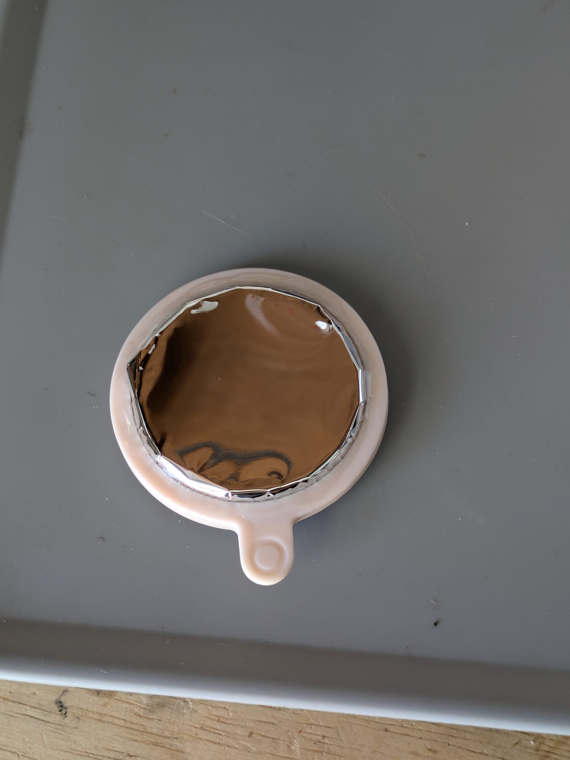
I was very tempted to use superglue on the ring before dropping it down onto the filter film (instead of small pieces of VHB double sided tape). I didn’t do that because I was worried it might not stick to the film, and I was also worried about CA glue offgassing when the filter was used in the sun. After I made this filter, I tested gluing the resin print to some cutoff film, and it appeared to work great. If I need to make another filter (or make one that looks a little smoother around the edges) I will try using CA glue instead, and make sure I put the whole filter out in the sun for a day before using it on my telescope to make sure the CA glue won’t offgas onto the lens.
However, even though the edges of the filter film look a little wrinkly, almost the entire surface of the optical path was very flat (but not overly tensioned) and the images through the solar filter look as good as any of my other smart telescopes produce, so I think functionally it worked great.
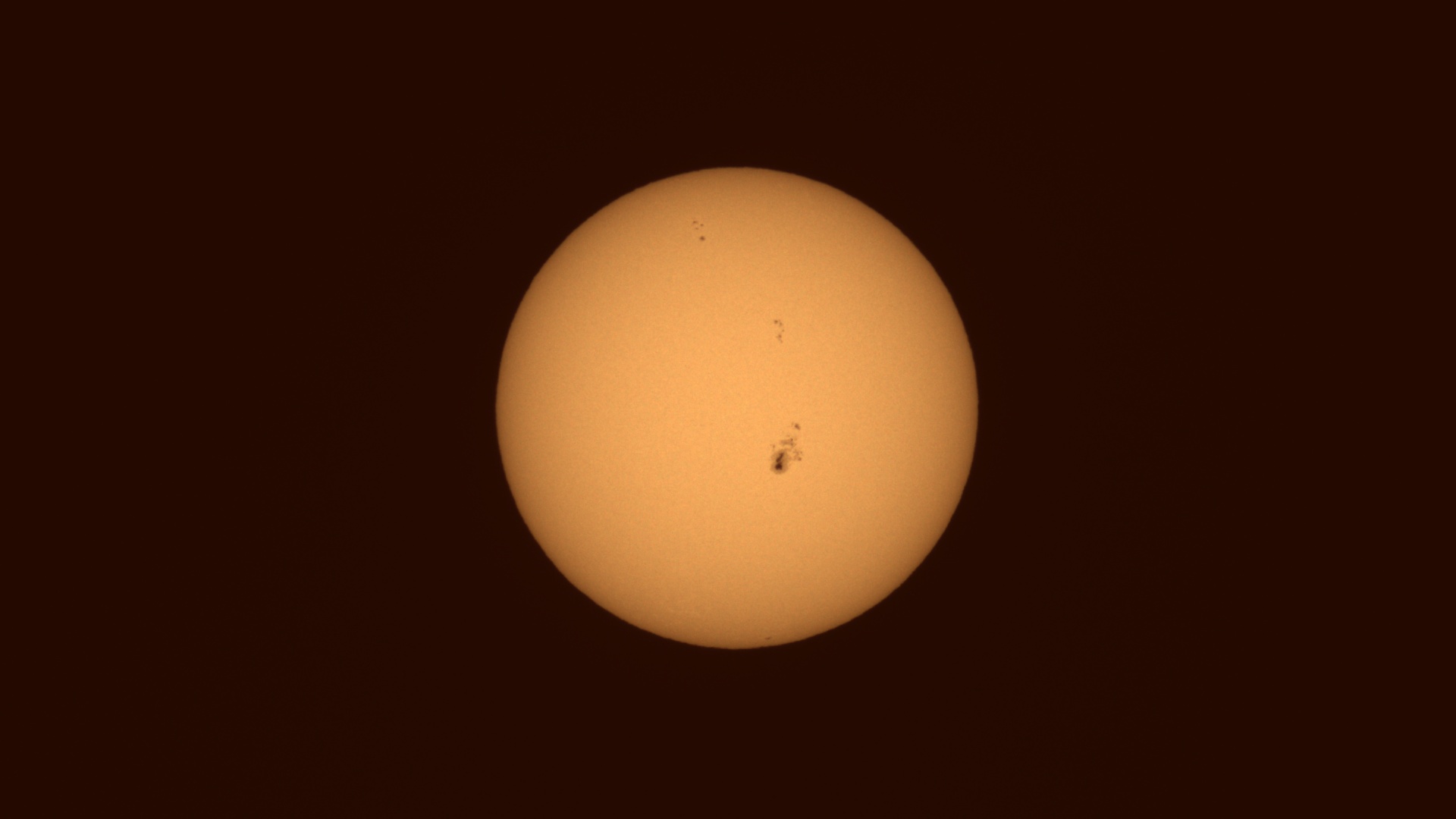
Sun stats: 0;0;0;0.003048, exposure: 300µs , gain: 0dB
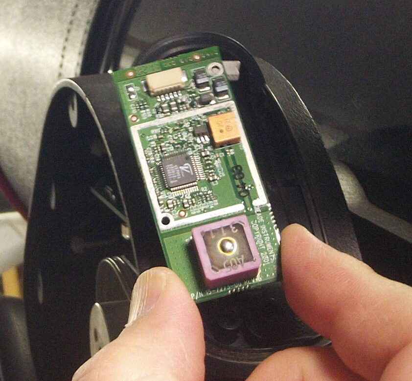
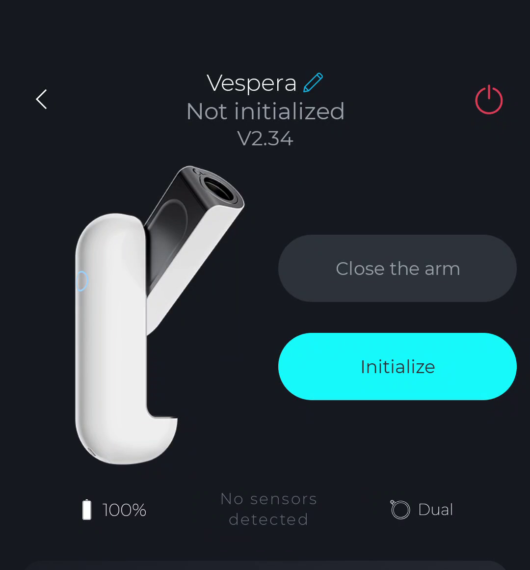
I used a 4.6 Kohm 1/8 watt resistor with the leads circled and soldered inside the filter holder to indicate to the Vespera that it had a solar filter installed, and it was detected correctly as soon as I plugged in into the telescope.
I purchased a used Vaonis Vespera smart telescope, but if I wanted to buy the “official” (and proprietary) Dual Band filter to use for imaging emission nebula, it would cost $400 USD!
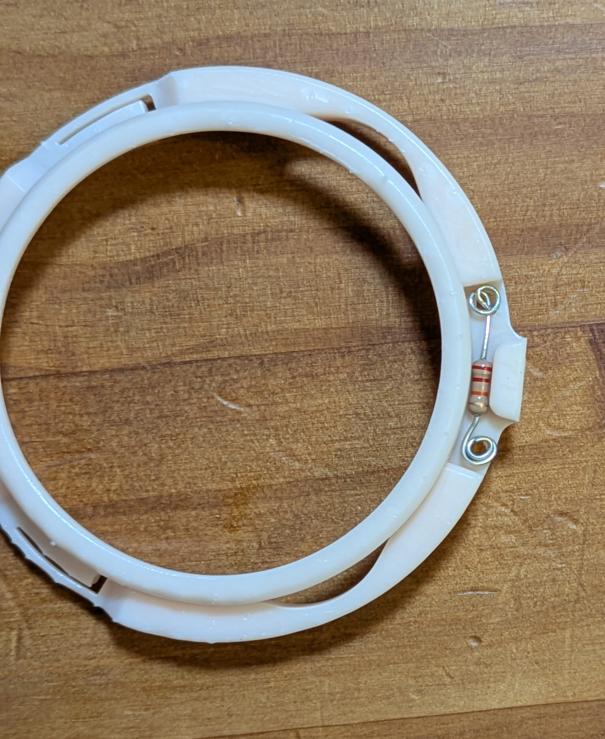
This especially smarts, as I already own a 2″ SVBony SV220 dual band filter that I use on my main telescope. Luckily for me, aureliend2000 has posted a 3D model on Thingiverse that allows you to create your own ‘Vespera compatible’ filter by screwing in any standard 2″ optical filter.
[And if you put a 24k Ohm resistor in the right spot, the Vespera automatically detects that a “Dual” band filter is installed, setting the gain of the camera appropriately.]
Here is a video showing the full process of how I made mine:
Here is a 48min exposure of the Rosette Nebula (from Bortle 7.5) without the Dual Band filter:
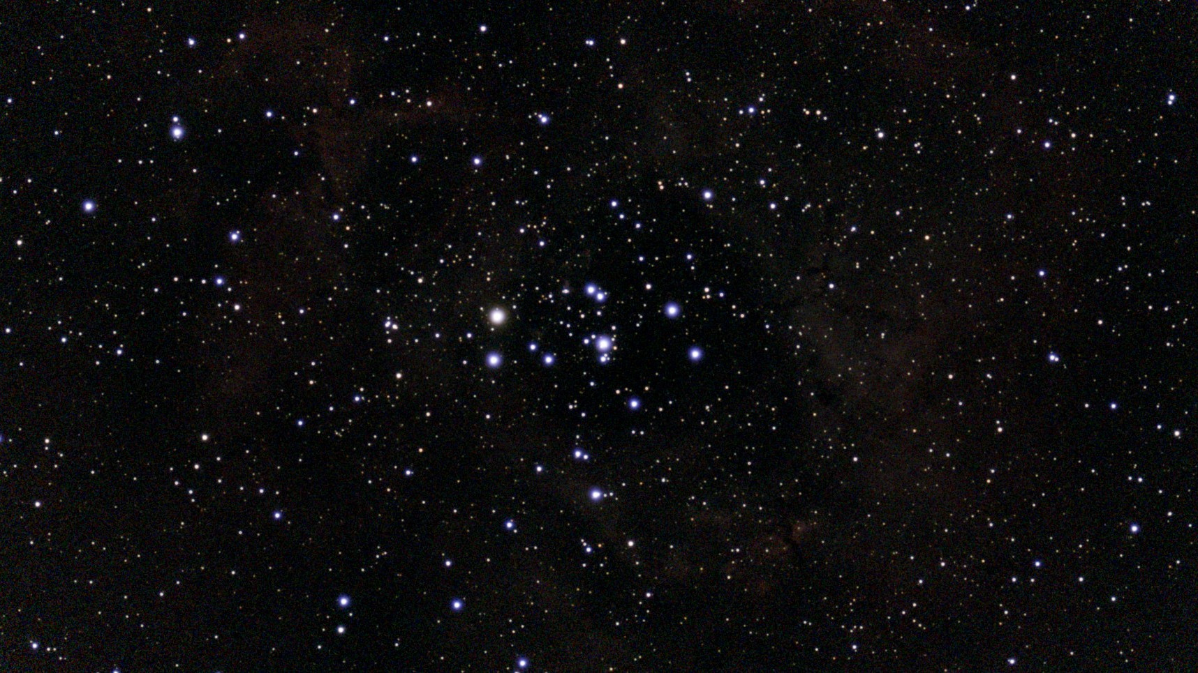
NGC2237_44 (290 exp)
And for comparison, here is a 48 min exposure WITH the SvBony SV220 dual band filter:

NGC2237_44 (287 exp)
And here is a 57 minute exposure of the Owl Nebula using the SV220 dual band filter:
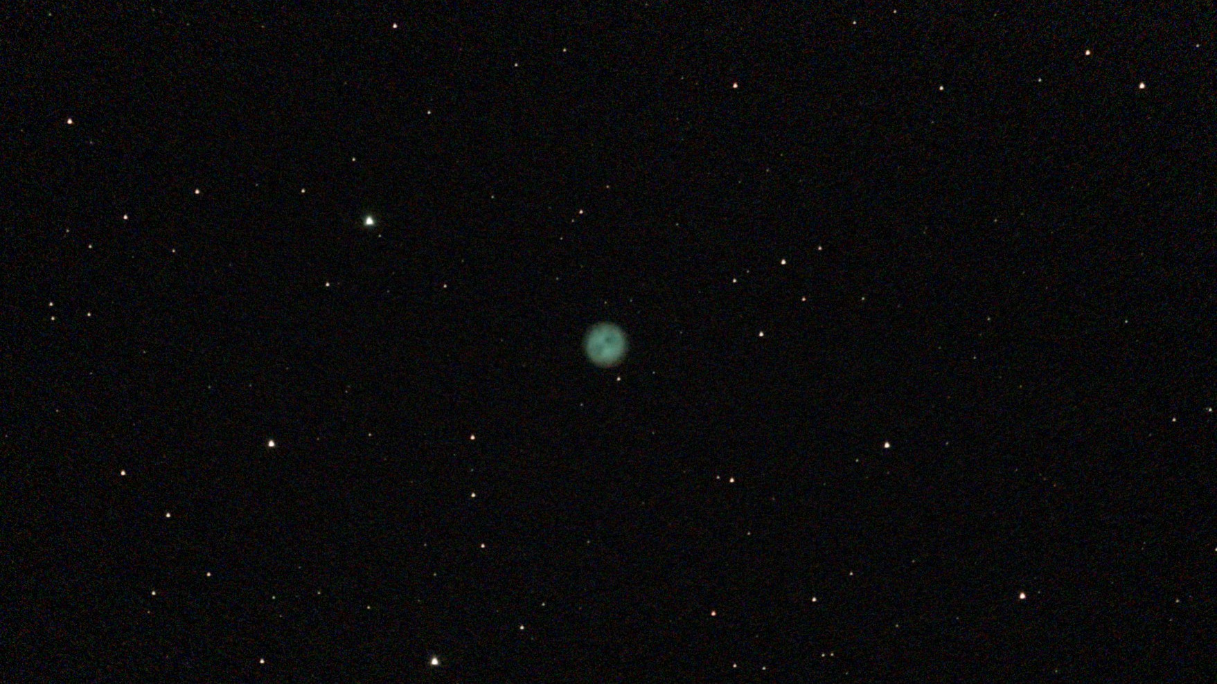
M97 (342 exp)
Considering I already had the SV220 filter, a 3D printer, and a 24k Ohm resistor “in stock” I’m very pleased with the ability to use a dual band on the Vespera without spending (any more) money. I’m so happy with the result that I’ve ordered a sheet of solar film and plan on making my own Solar Filter so I can use the Vespera to image the sun. [Yes, my Zwo Seestar S50 came with a solar filter and a built in light pollution / DB filter….but the optics, tracking, and software of the Vespera are all just slightly nicer, and since I got it used the cost wasn’t outrageous.]
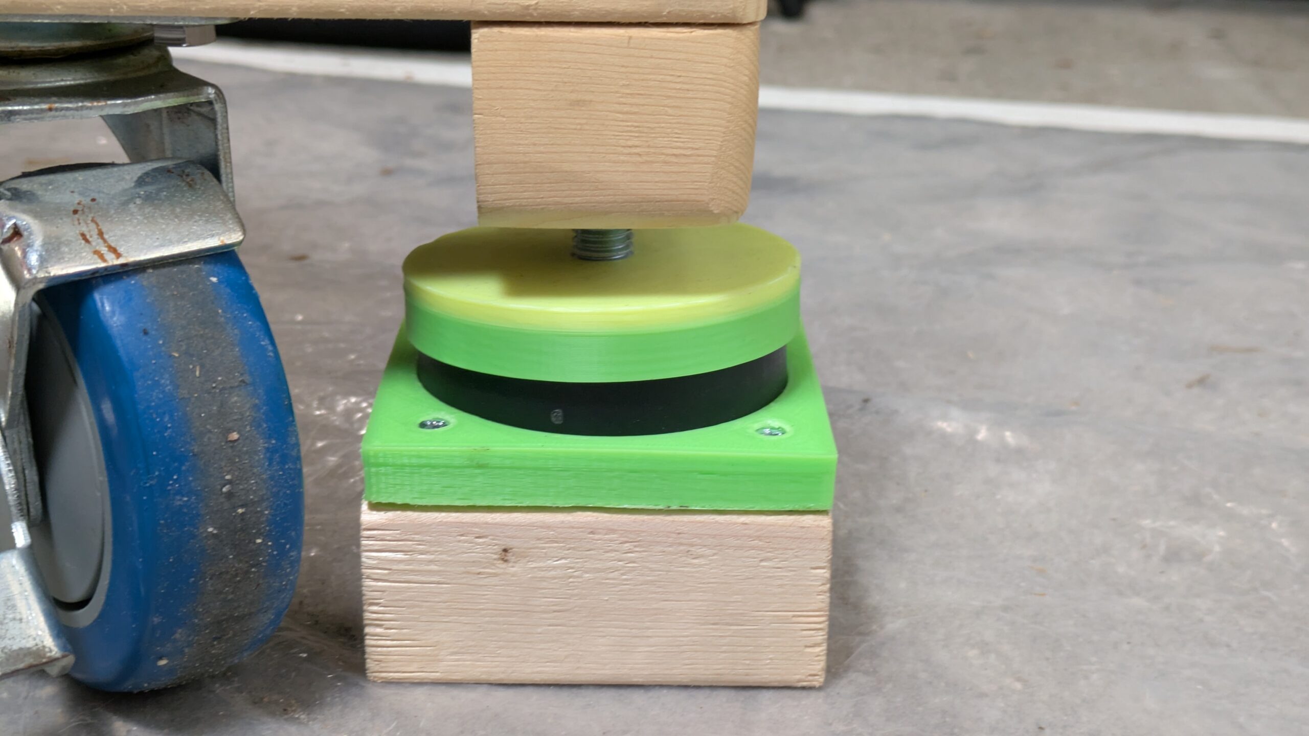
I want my telescope to be polar aligned when using it. To do this, I need to have the base accurately pointing exactly towards the north pole (in the Azimuth direction) and the Altitude of the wedge the same as my latitude. [This essentially means that I need the tripod base to be exactly level.]
Getting the tripod level is easy, as I have 3 leveling bolts built into the ends of my home built rolling dolly and a bubble level on the telescope wedge. However, to get the AZ orientation correct, I need to reliably place at least 2 of the alignment bolts in the exact same spots on my patio every time I wheel the telescope outside to use it.
To make this easy, I built these alignment jigs. They consist of a square piece of 2×4 (3.5″ by 3.5″) which rest inside a white square of gaffers tape. The square gaffers tape lets me put these wood base blocks at the exact same point each night. But, I really need to align the 3 leveling bolts, not just the wood blocks. So I designed and printed two 3D printed jigs. One to align the anti vibration puck to the center of the wood spacer block, and one to align the bolt to the center of the anti-vibration puck. The combination of jigs allows me to place the three leveling bolts (and hence, the dolly, and tripod) at the exact same location every night.
You can watch the video below to see how this works in practice.
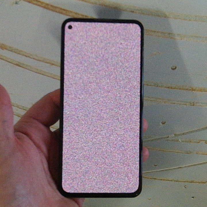
My wife’s Google Pixel 5A phone developed a problem where the screen would “flash” between a colorful snow pattern and was it was supposed to be showing. It started out slowly, with intermittent flashes, but quickly got worse where the screen was barely ever showing what it was supposed to. [It also does not accept touch input events when “flashing” the colored snow pattern..]
I was able to retrieve the data off of the phone by heating the entire phone up, but this was a temporary fix as the problem returns as soon as the phone cools down.
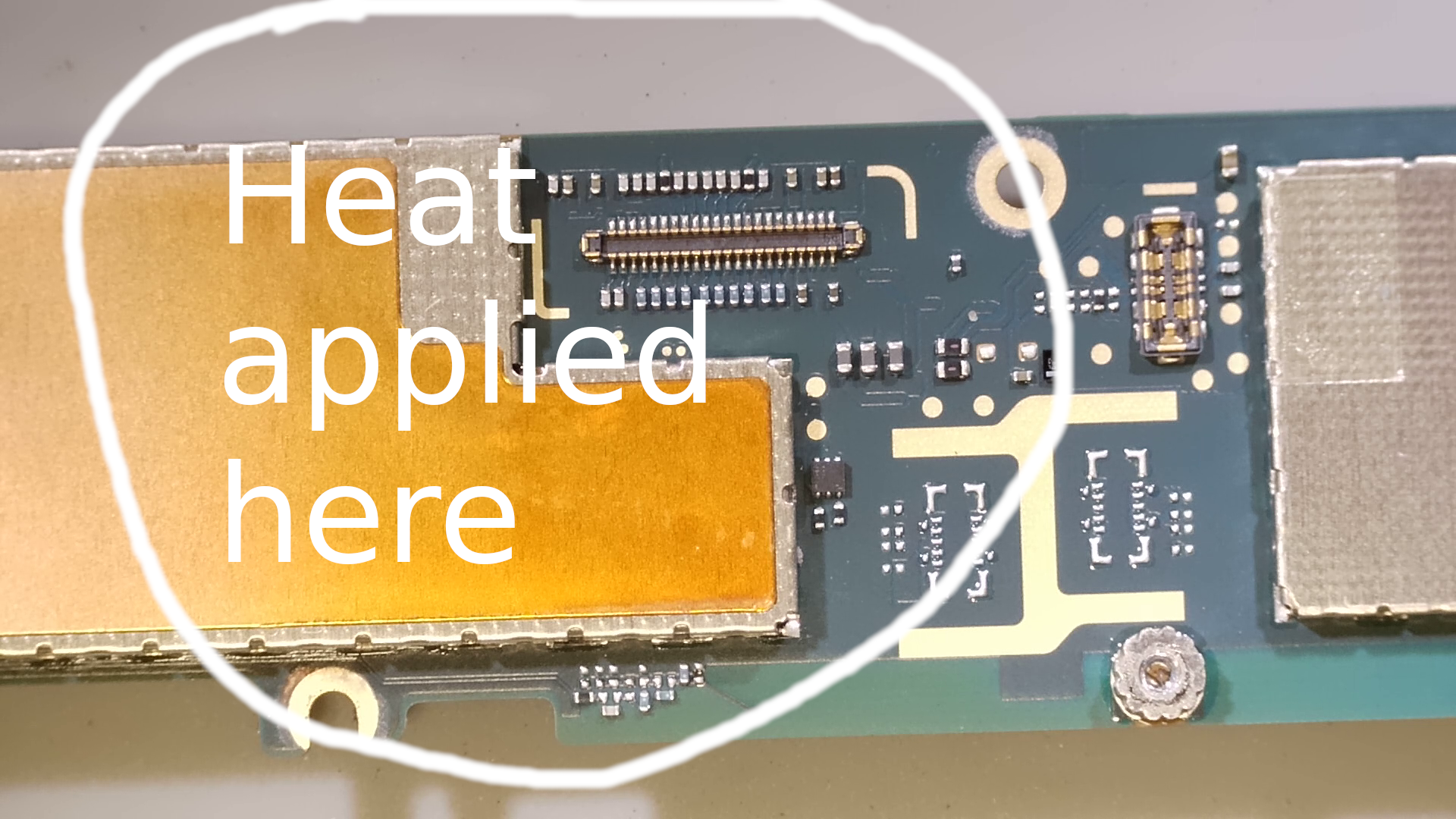
I was able to fix the problem (hopefully permanently) by completely disassembling the phone, extracting the motherboard, and hitting it with 5 minutes of heat from a 300 deg c hot air rework station. (I aimed the hot air at the video connector, and then at the covered set of chips right above the video connector (opposite from the battery connector), as I figured that was the most likely location for the video graphics chips. I still don’t know which EXACT component had the problem, but allowing the solder joints in that general area to re-flow appears to have fixed the problem, as when I re-assembled the phone it is working perfectly at room temperature.
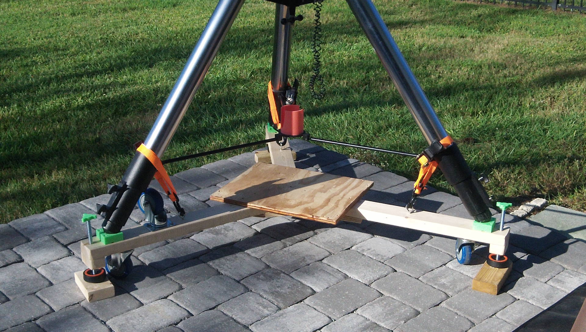
I built my own Tripod Dolly with casters & Leveling bolts (out of 2×4’s and plywood) for my Meade LX-200 12″ with Giant Field Tripod (the one with the 3″ diameter legs).
I was originally thinking it would be just so I could play around with the telescope (move it in and out of the garage) and get a feel for things until I decided what commercial dolly / truck / cart to buy, but I’ve been so happy with the results that I think I’ll just use it permanently.
I’ve got a short 5 minute intro video here (which links to a full 40 minute how to build step by step video if you decide to follow along and build your own):
Also of potential interest to people with the Meade Giant Field Tripod is that I modeled the tip of the tripod legs and designed a 3D printed bracket for holding the tripod tips securely in place on the 2×4’s…[Of course, you could just drill a 1″ hole at a 55 degree angle, but if you’ve got a 3D printer everything needs a custom bracket….]
You can find the 3D model & OpenSCAD design file on Thingiverse here: https://www.thingiverse.com/thing:6826864