UK Denford Micromill 2000 (February 2002 dispatch date) interior photos

Steve is working on a UK (240 volt) Denford Micromill 2000 (February 2002 dispatch date). When referring to my four part series( 1, 2, 3, 4) about how I got mine working under CNC control, he sent me some photos of the inside of his unit which I am posting here with his permission just in case they can help others working with one of these units.


Denford Micromill 2000 January 2003 dispatch date – SGR location

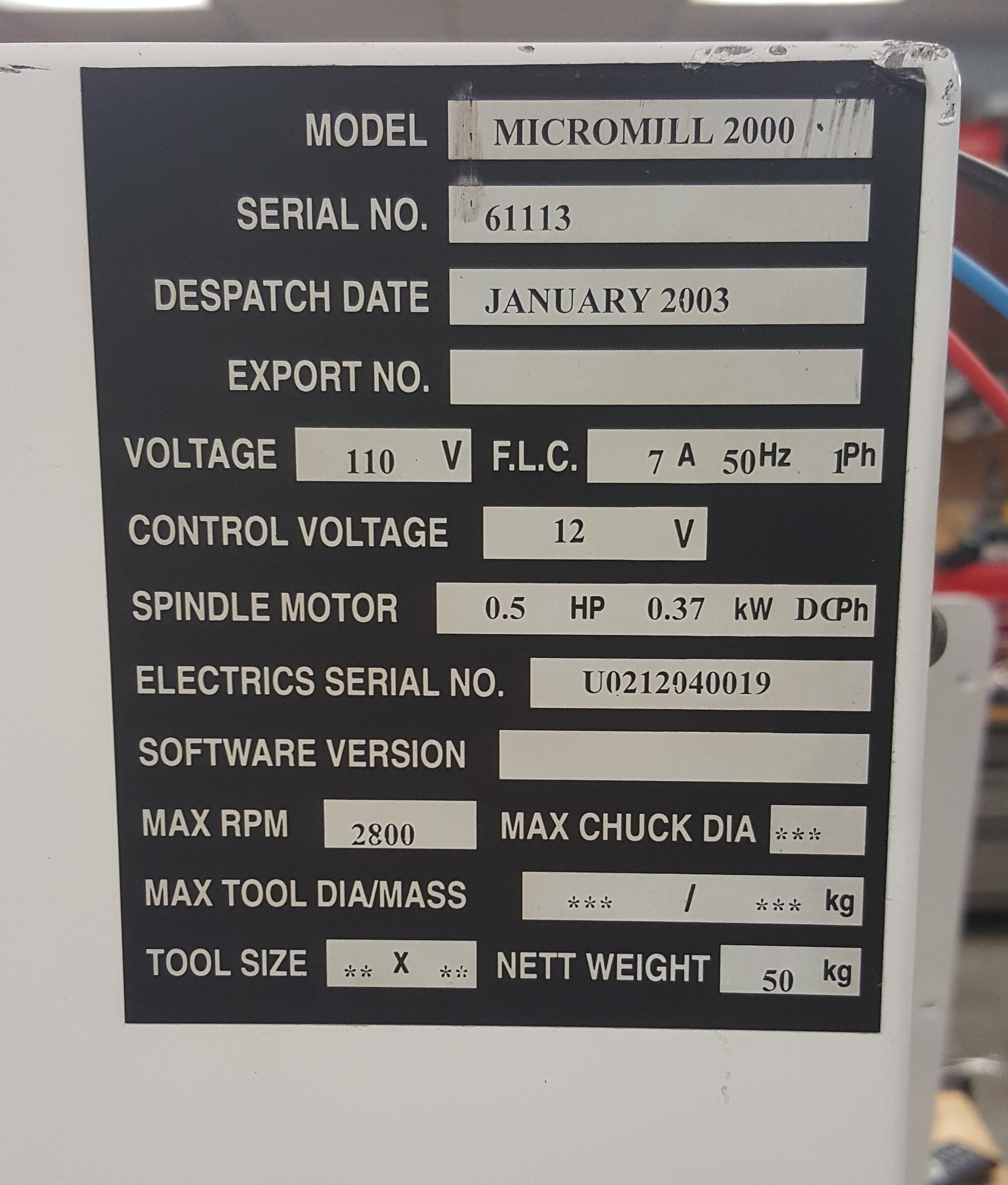
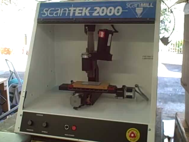
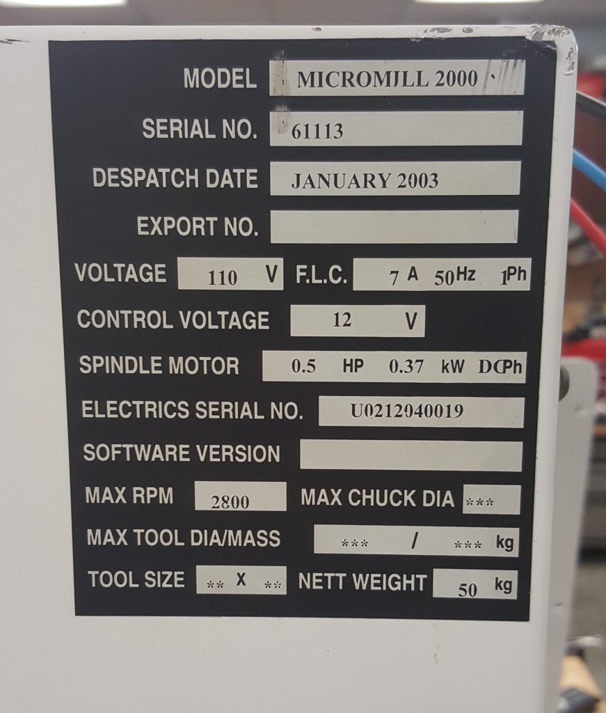
Cliff Burger is part of a makerspace ( http://www.tcmakerspace.com ) which had a Denford Micromill 2000 (January 2003 dispatch date) donated to them. When referring to my four part series( 1, 2, 3, 4)   about how I got mine working under CNC control, they noticed a few differences with their model and wanted to share that information.

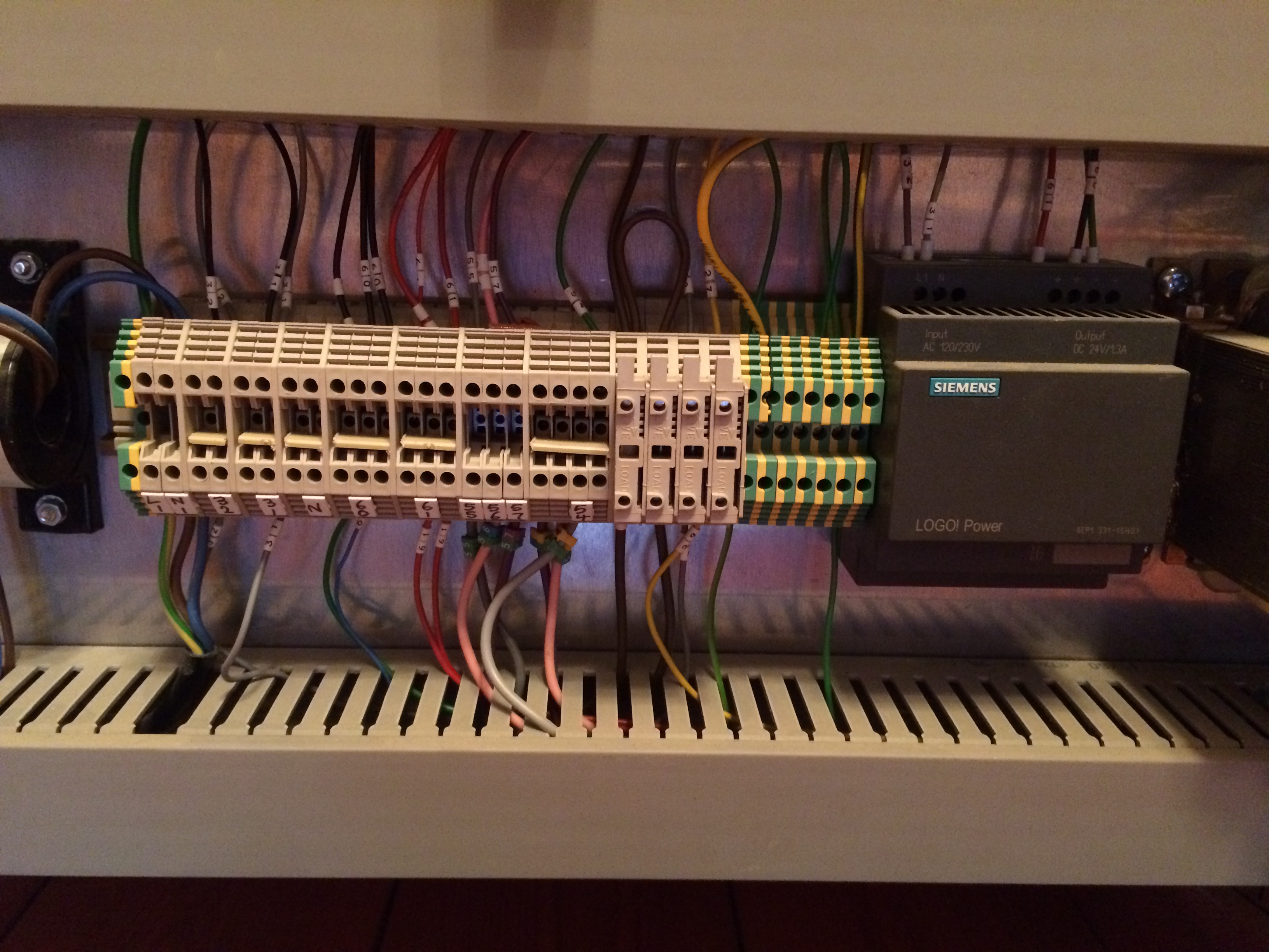
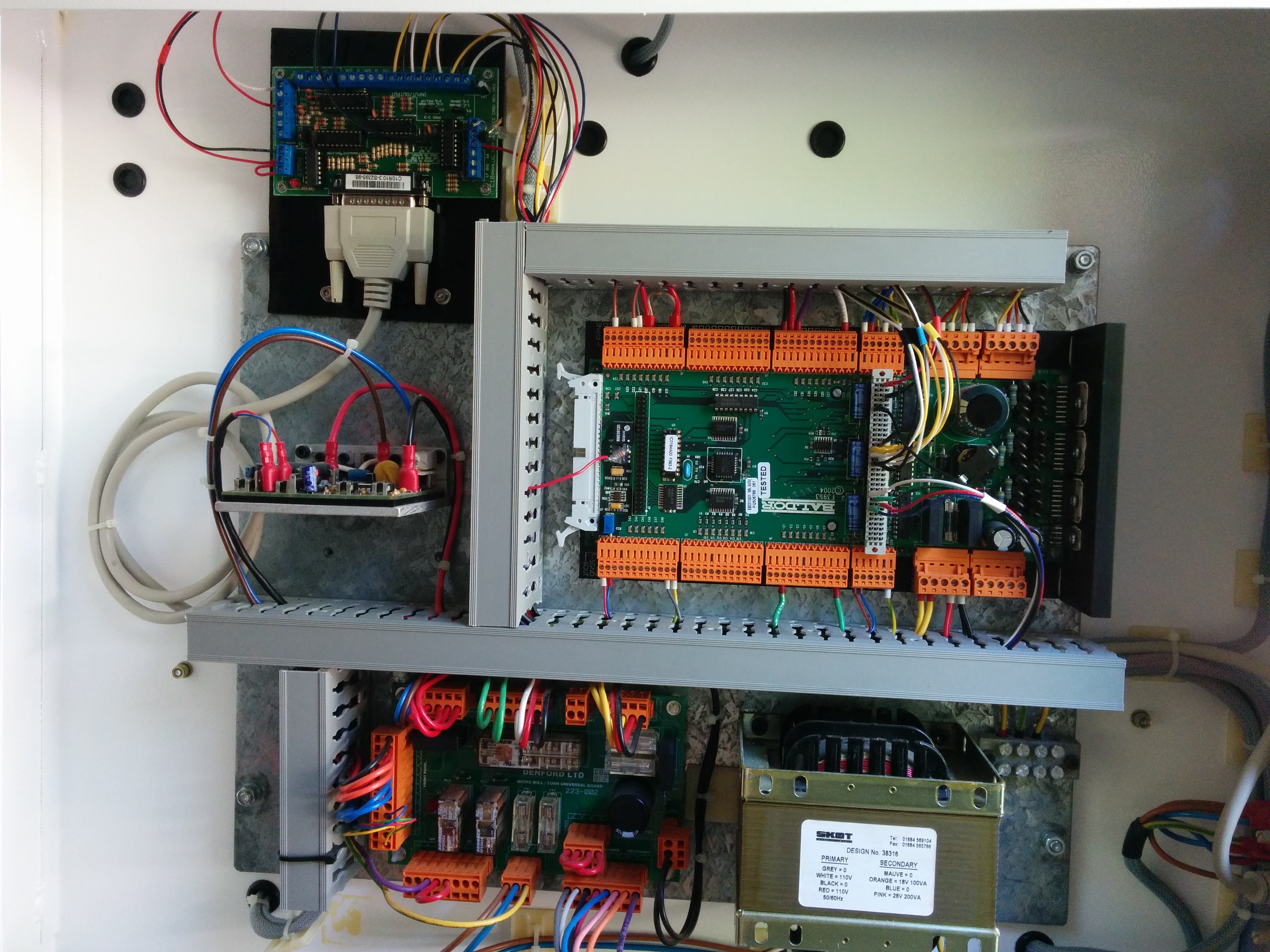
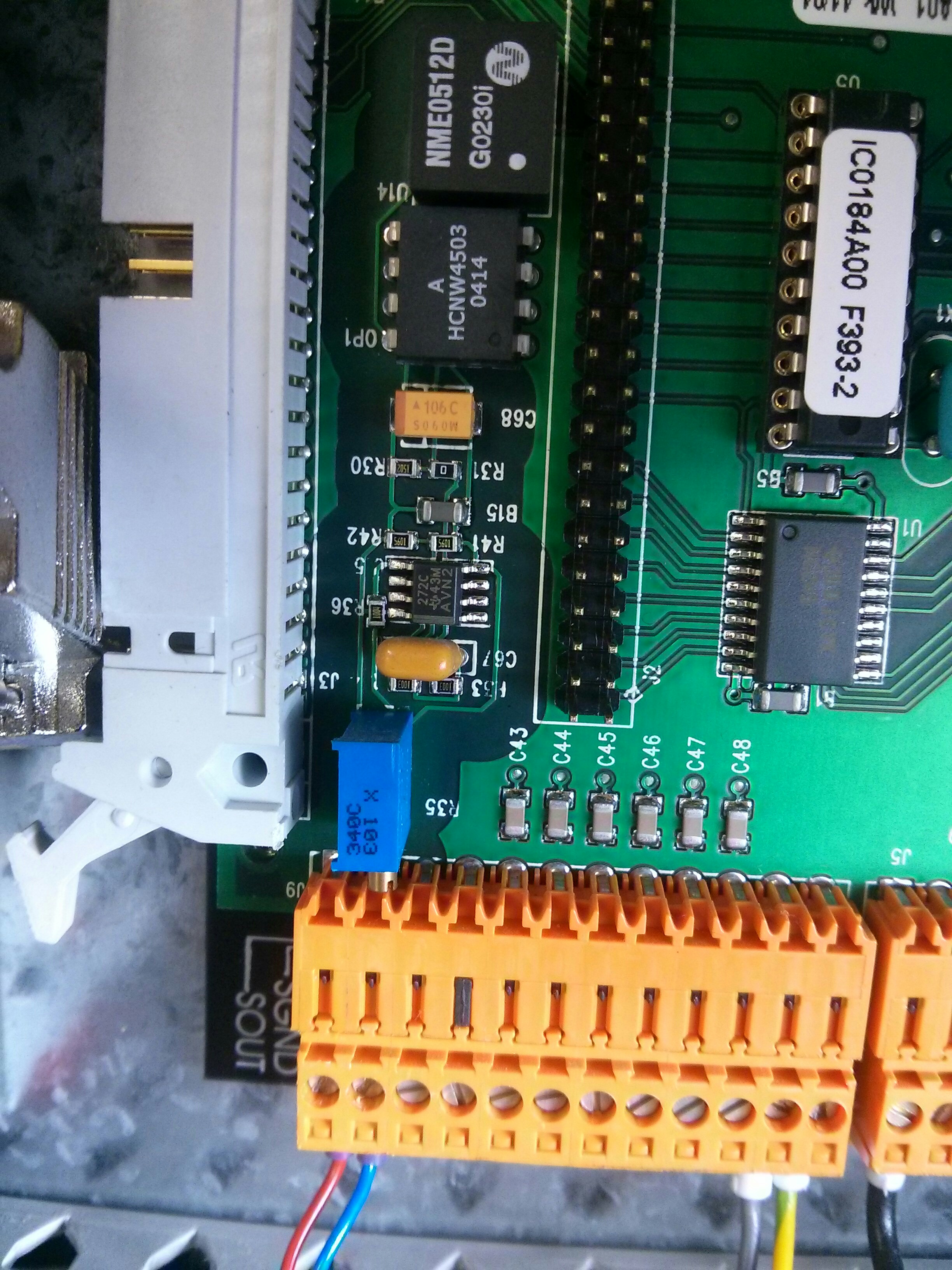
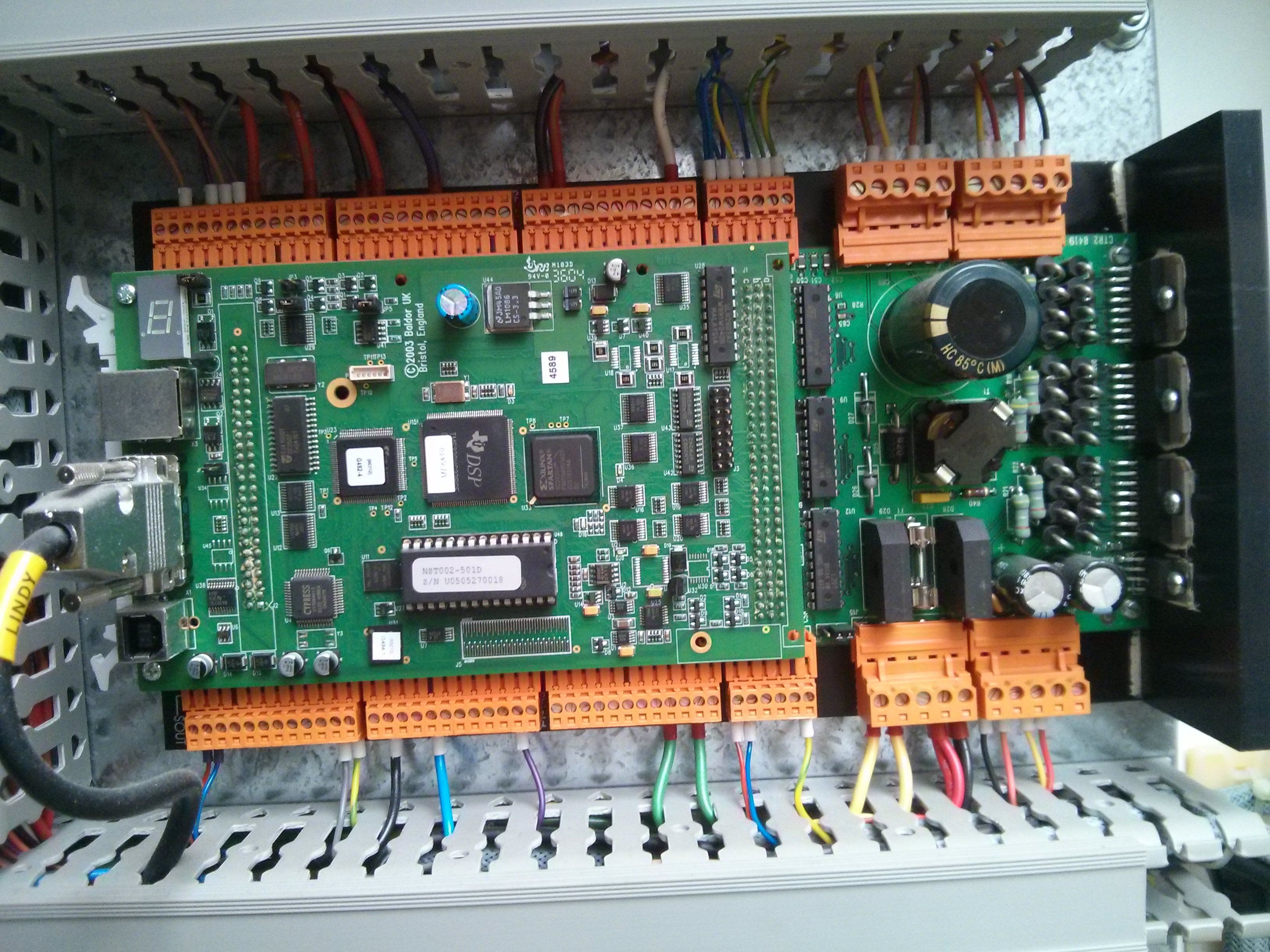
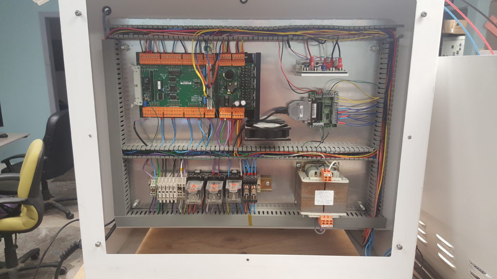
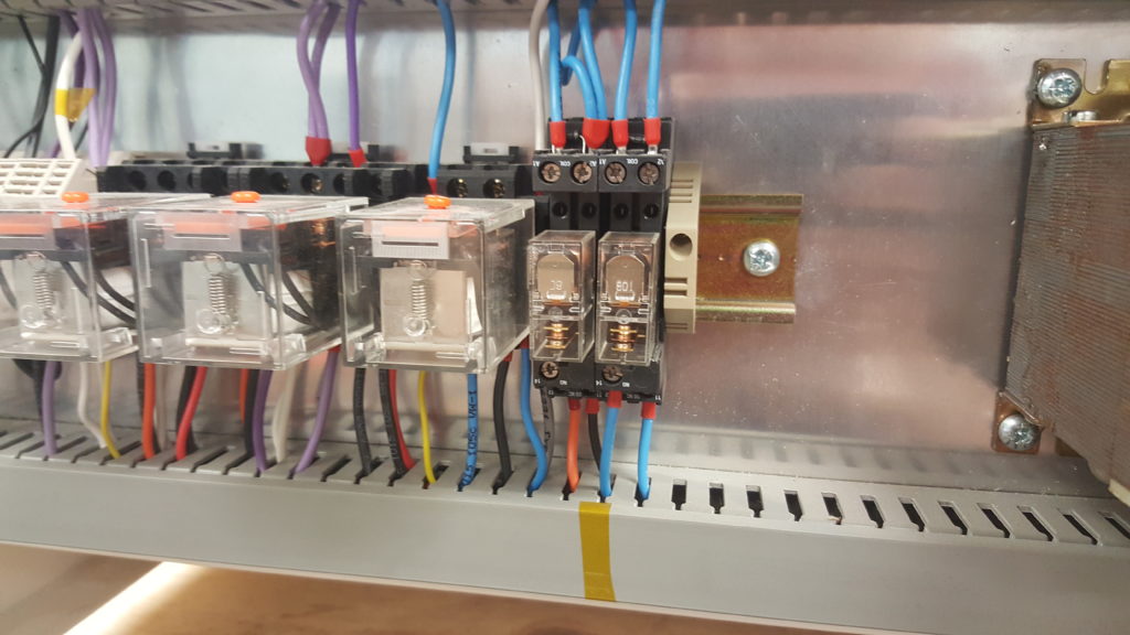
Instead of having a custom made relay & power board, their mill has it’s relays mounted to a DIN rail (bottom left of the case in the image below).   The spindle go relay (SGR) is located in the 2nd from the right position.

A quote from Cliff:

On the DIN rail, the spindle activation relay is the second one in from the right. It’s a 12v relay with the ground for the coil being controlled by the C6 pin. However, currently the relay never sees a 12V signal either. Not sure if it’s something wrong with my board or it’s waiting for another command signal before it sends the 12V out as well. Either way, I’ll likely just get a 5V relay and switch it right off the BOB, but for the time being I’ve moved the orange wire from the “14” position to the “12” position to supply power to the board at all times.


Cliff also sent along his mach3 config file, which you can download here (note, you will have to remove the .txt extension from the file to use it.)   Denford.xml.txt

He has the following caveats:

Things to note about the mach3 config:
1) My limit switch are on different pin numbers due to me chopping 1 wire a bit shorter than I should have (oops!).
2) default units are in inches so the steps per INCH are correct, but may need slight tweaking for each application.
3) backlash settings will need to be measured for each mill, or disabled.
4) I’m running a UC100 UBS adapter board so Mach3 may give an error message the first time you open it with this config file.

MicroMill Mach3 / LinuxCNC conversion complete

I have mounted the parallel port break out board inside the enclosure of my ScanTek 2000 (Denford Micromill). I routed the parallel port cable out to the previous DB25 (RS-232) outlet on the case and sealed up the back.

bob_mounted

With the built in wire management trays, the job looks almost professional…except for the fact that I used a triangular piece of 1/4″ acrylic scrap I had for the mounting plate, so I had to orient the break out board at an angle. But since it’s inside the case, nobody can see it anyways. bob_mounted_closeup


parallel_port_cable_inside_panel

Outside the case, the only visible difference is that I took off the black “RS-232” sticker that used to live next to the DB-25 connector. Continue reading

ScanTek / Denford Micromill 2000 bent spindle motor bracket

spindle_motor_at_angleWhen I purchased the ScanTek 2000 Scan Mill (A rebranded Denford Micromill) from a surplus supply house, the spindle motor was at an odd angle and the drive belt had frayed (probably due to the angle).

When   I took the motor off, it was clear that the problem was a bent bracket.
bent_original_bracket
Since I needed to purchase a new drive belt ( Sherline PN 40040   – $9) I decided to just buy a new Sherline spindle motor support bracket (PN 40020 – $7 ) at the same time because it was relatively inexpensive.
Continue reading

How to convert a Denford / ScanTek 2000 Micromill to LinuxCNC / Mach3 control: Part 4 — Spindle Speed Control

In part 1 of this series I showed how to get the X/Y/Z steppers moving. In part 2 I hooked up the home and estop switches. In part 3 I got the spindle go relay working so that I could turn the spindle on (at full speed) or off. In this post, I will show how to get PWM speed control of the spindle working.

The Balfor NextMove ST card has an output (SOUT & SGND) line that provides an isolated 0-10 volt signal (at low current) suitable for controlling a spindle motor driver board. (0 volts is stopped, 10 volts is full power) In the bottom left of the picture below you can see the small blue and red wire leading away from SOUT & SGND.

It does this by using a DC/DC converter (NME0512D) to provide an isolated (floating) 12 volts, referenced to the SGND connector. A TLC272C OpAmp chip integrates a PWM signal (taking into account an offset adjustment from R35, the boxy blue variable resistor near the SGND/SOUT pins) into a 0-10 volt signal.
HV_analog_0-10_output_circuit
Continue reading

Micromill test run with G-code

Now that I have the hardware in place, I’m working on the software side of things. I installed and configured LinuxCNC to control the Mill. (Mach3 was easier to get set up and running initially on the trial license, but they do require you to run windows…and the GUI is a bit garish.) In this video you can see the mill cutting out a circular pocket (in the middle of the air, as I’m testing CAM software, software limits, etc as well.)

You might notice that the belt has been removed between my spindle and spindle motor. When I purchased the machine the spindle motor was at a slight angle, which I traced to a bent spindle motor bracket.   As a new bracket costs under $7, I decided to buy a new one instead of trying to bend my existing one back into shape. The replacement bracket appears to be machined slightly better overall anyways. Until it arrives, I don’t have the spindle hooked up.

IMG_20160122_213513


How to convert a Denford / ScanTek 2000 Micromill to LinuxCNC / Mach3 control: Part 3 — Spindle Motor Control

In part 1 of this series I got the stepper motors for the 3 axes moving. In part 2 I hooked up the home and E-Stop switches. In this post I will describe getting the spindle motor to turn on (and off!) controlled via the parallel port break out card (I’m using Pin 1).

You can watch the video here, or read the text and see the photos below:

To enable the spindle motor, two things have to be done. First, the Spindle Go Relay (SGR) must be turned on, which provides 120 volts AC to the spindle driver board. Second, the spindle driver board input needs a 10 volt input to turn on the output (to the spindle motor) at full blast. The photos below are of my Dispatch Date 2005 mill, but other mills from Denford are similar in their general operation. [If you have an earlier dispatch date mill, you may have a DIN rail of relays mounted individually instead of this custom PCB of relays. Check out this post for a few photos and info about the SGR in that situation.]
Continue reading

How to convert a Denford / ScanTek 2000 Micromill to LinuxCNC / Mach3 control: Part 2 — Home switches & E-Stop

Part 1 told how to make your computer output commands to the 3 stepper motors controlling the X,Y,Z axes of the mill so that you could jog them around under computer control.

This post deals with getting input from the switches on the mill to your computer.

I am interested in getting input from 4 switches on the mill. First, the Emergency Stop button on the front panel is great to have operational!

estop

Continue reading

How to convert a Denford / ScanTek 2000 Micromill to LinuxCNC / Mach3 control: Part 1 – 3 Axis control

How to convert a Denford   / ScanTek 2000 Micromill to LinuxCNC / Mach3 control

Part 1 – 3 Axis control
Video here, details below


My ScanTek 2000 ScanMill (A re-branded Denford Micromill 2000) has a dispatch date of 2005, which means that it’s main controller is a Baldor NextMoveST card. This card supports USB as well as RS232 control signals, and runs a custom (MINT) programming language that can offload machine control from the host computer.

Baldor NextMoveST

You can actually download the MintNC development tool from the Baldor website that allows you to upload custom Mint programs to the card, and could make it (for example) do some simple operations offline with no driving computer. However, I am not interested in writing Mint code to interpret g-code, so I’m going to set it up so that LinuxCNC (or Mach3) can control it via a parallel printer port.
Continue reading