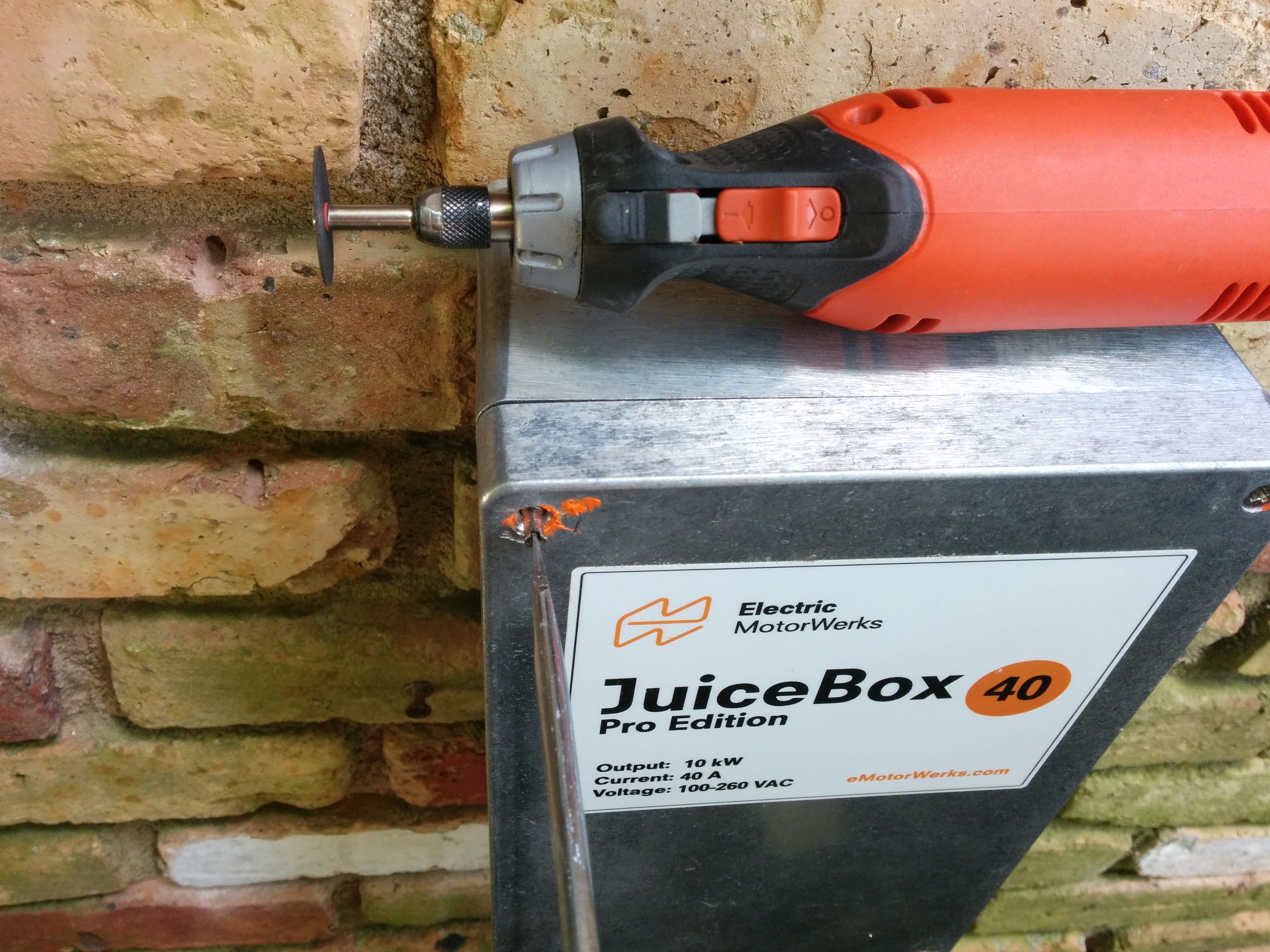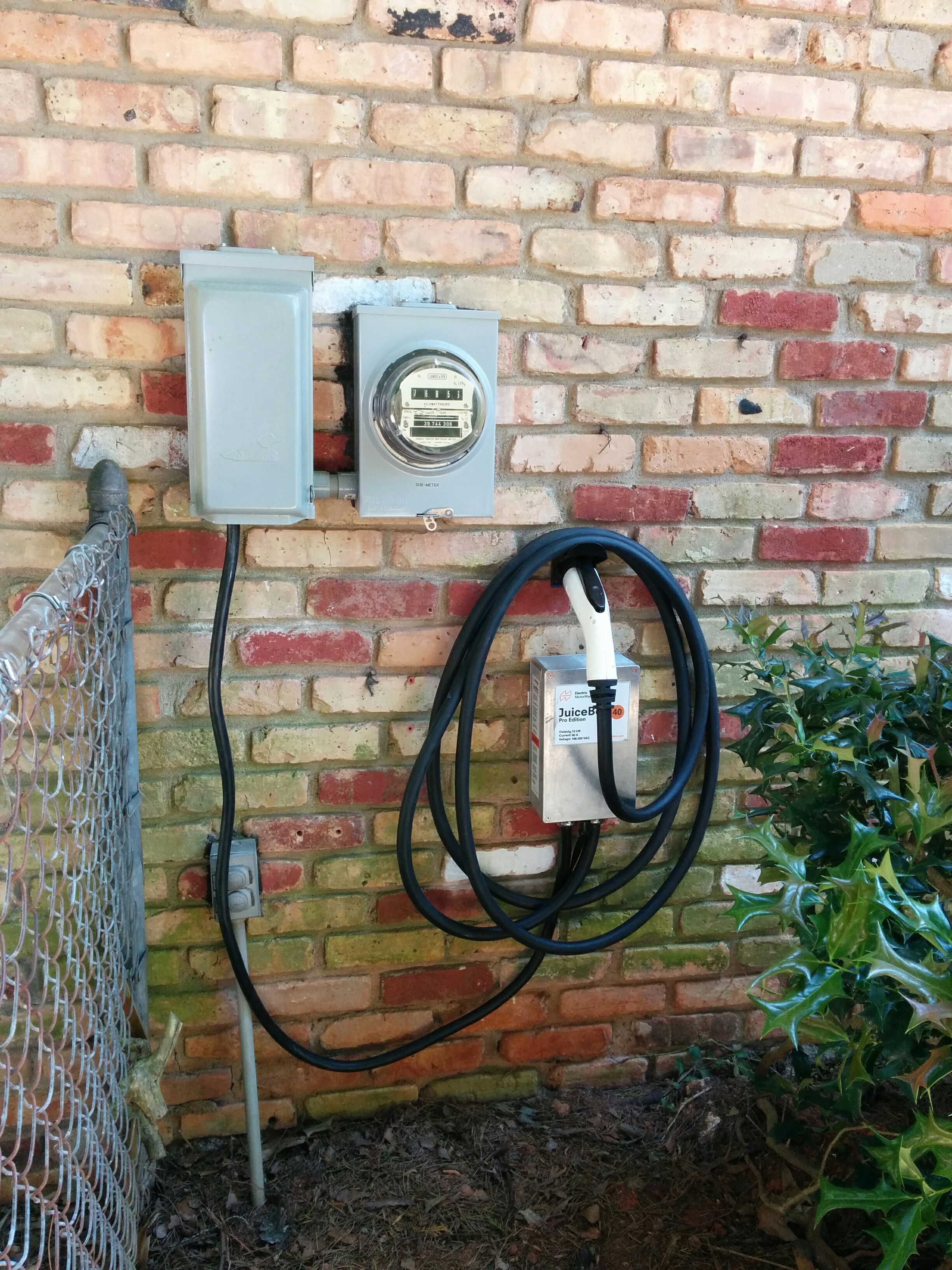
I’ve been using an Electric Motor Werks JuiceBox Pro 40 to charge the truck for the last six months. It worked just fine most of the time, but suffered from intermittent GFI trips that would cause the wifi module to turn off entirely (going offline and stopping the charge) very occasionally. After flashing the firmware didn’t fix the issue, they sent me a replacement unit. (Pictured above).
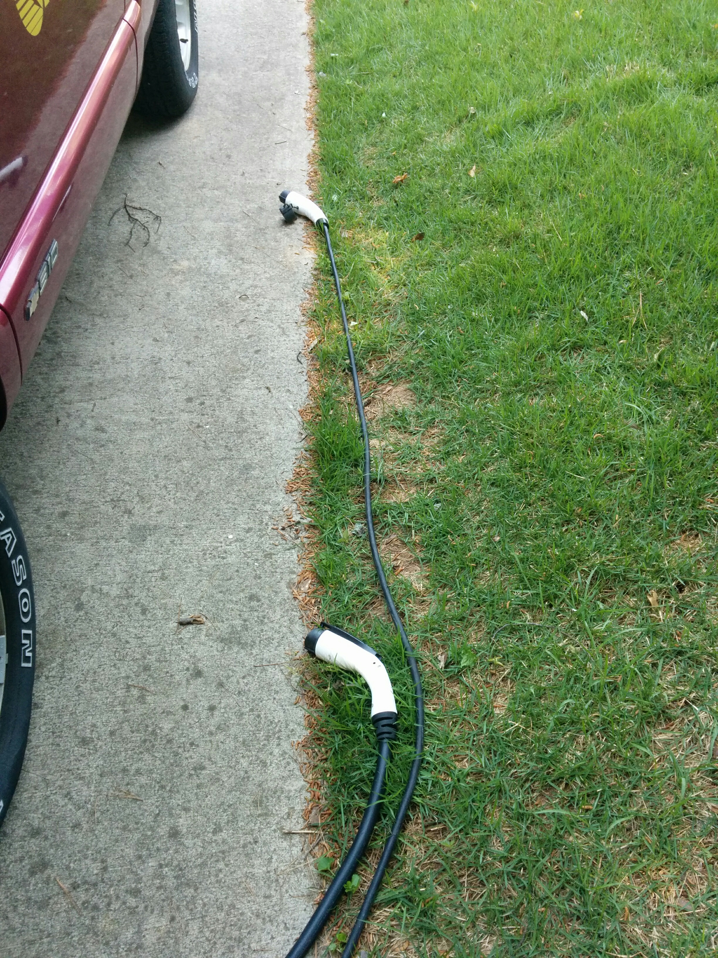
You can read all about the old unit here. The new unit has a slightly newer version number (v8.14.07) and the power cable going out to the J1772 gun is shorter (looks to be 18′-20′ instead of 25′) and MUCH thicker (marked as 8 GA wires for power, which matches the wires used to supply my NEMA 14-50 outlet). I have some photos of the differences here:
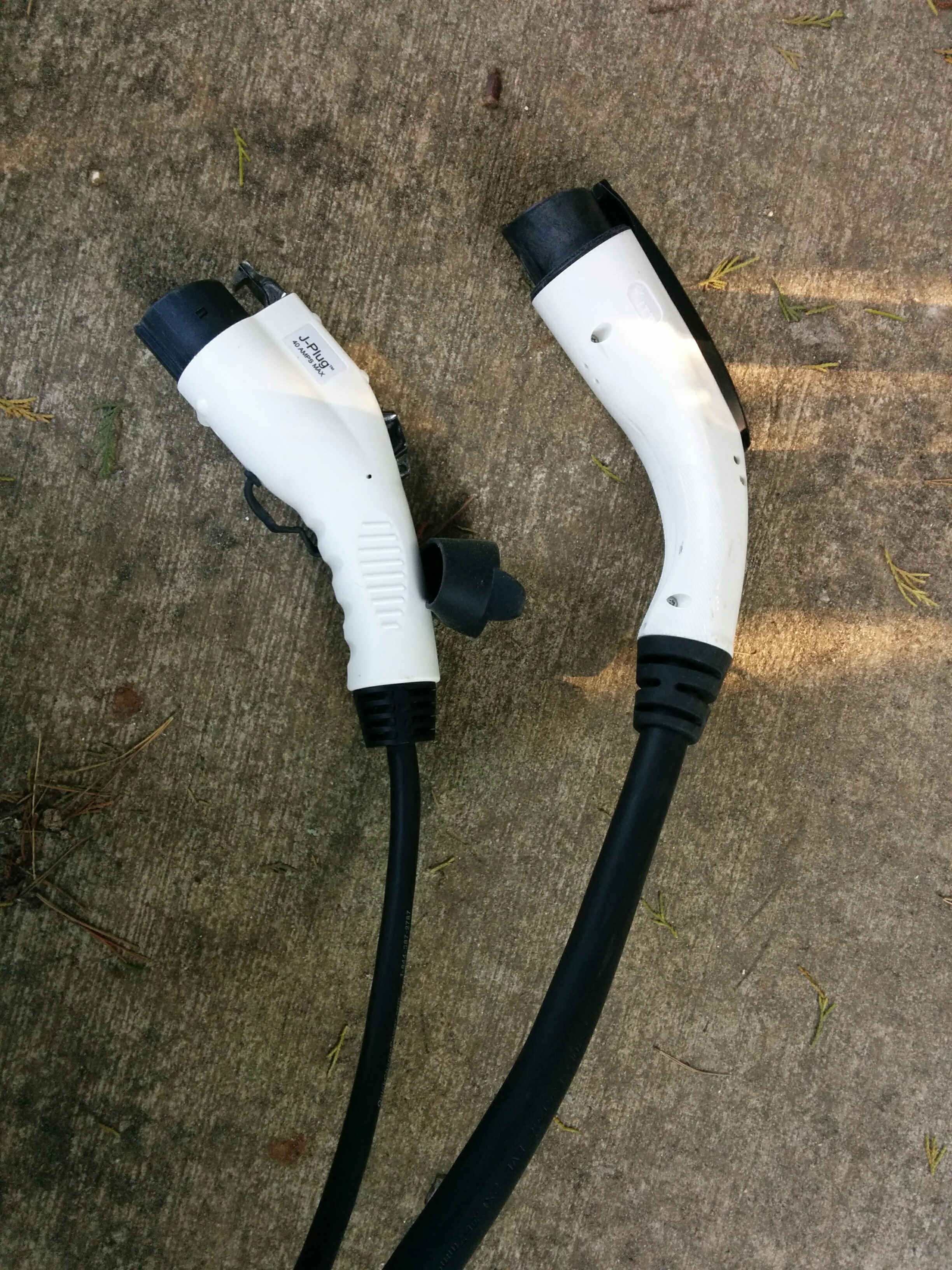
Poking around the Electric Motor Werks website, the “thick” cable and gun appears to be what the current JuiceBoxes come with by default, but they have an option where for an extra $29.99 you can equip your JuiceBox with “Flexible J1772 Cable” described as follows:
“Outfit your JuiceBox with a flexible & thin 40A 25FT non-UL J1772 (output) cable!
For those who value portability, or ease of cable manipulation, we are glad to offer a highly flexible and thin output cable option. With the addition of this option, your fully warrantied and assembled JuiceBox will come ready to go with a 25FT 40A portable spec output cable.
Please note that this cable is not UL rated, and not designed for compliance with national electrical standards. It is tested as safe to use for the power rating presented. Please note the cable you receive may not appear exactly as pictured – though dimensions and cable materials will be consistent.“
So it may be that my original unit came with the “flexible” cable by default, but the new unit comes with a larger UL listed cable. (The cord I got on the replacement unit is shorter than my original by a good five to six feet.)
GFI cause update:
I have identified the cause of the GFI events (my TSM2500 chargers cause a GFI event when they shut down due to overheating.) The new charger still gets knocked “offline” when a GFI event happens, but it appears to recover on it’s own without needing me to power cycle it.