(Or, “My UPS is bigger than yours, Na Nah Na Na Na!”)
Most consumer grade Uninterruptable Power Supplies (UPS) are designed to give you just enough time to save your work and shut down your computer, and run off of a 5 to 7 Amp Hour 12 volt battery (and because they are discharged so quickly, the pieukert effect means that you don’t get anywhere near the full 5-7 amp hour capacity).
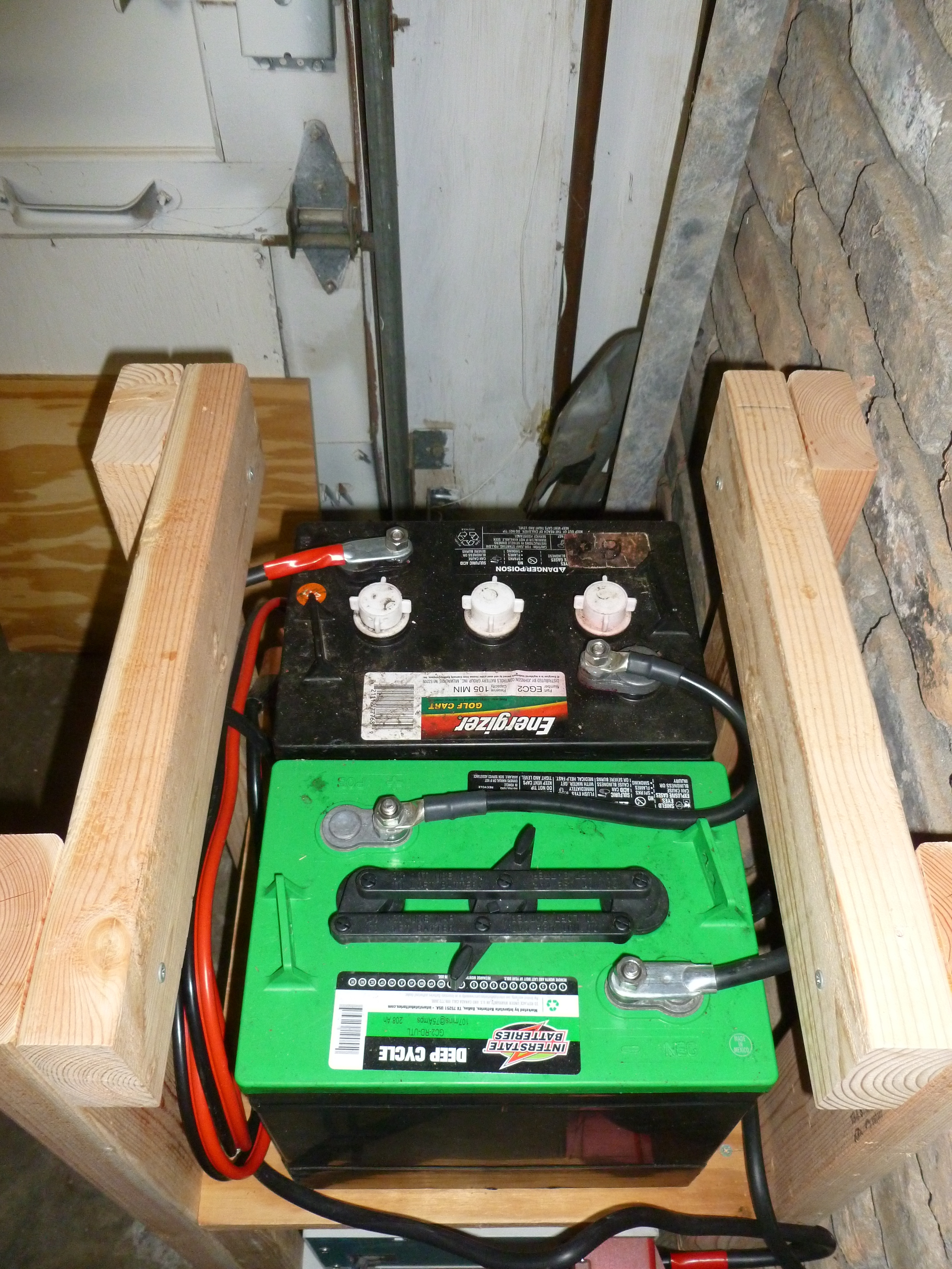
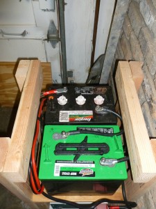
The battery core of my UPS is a pair of two six volt GC2 deep cycle golf cart batteries rated at a 208 Ah capacity. Running a standard computer system, they will be well within their 20 hour rate curves, but as they can deliver 75 amps for 100+ minutes they can also run higher draw appliances such as a toaster oven or refrigerator if needed.
These are the same type of batteries as power my electric pickup truck, so I have a ready supply of halfway-used batteries. They can also act as a backup battery for my truck if one of the traction pack batteries need replacing. In addition, if we have a freak ice storm that takes out power for multiple days, I can swap batteries into the UPS from my truck and keep the refrigerator and some lights running for a week.
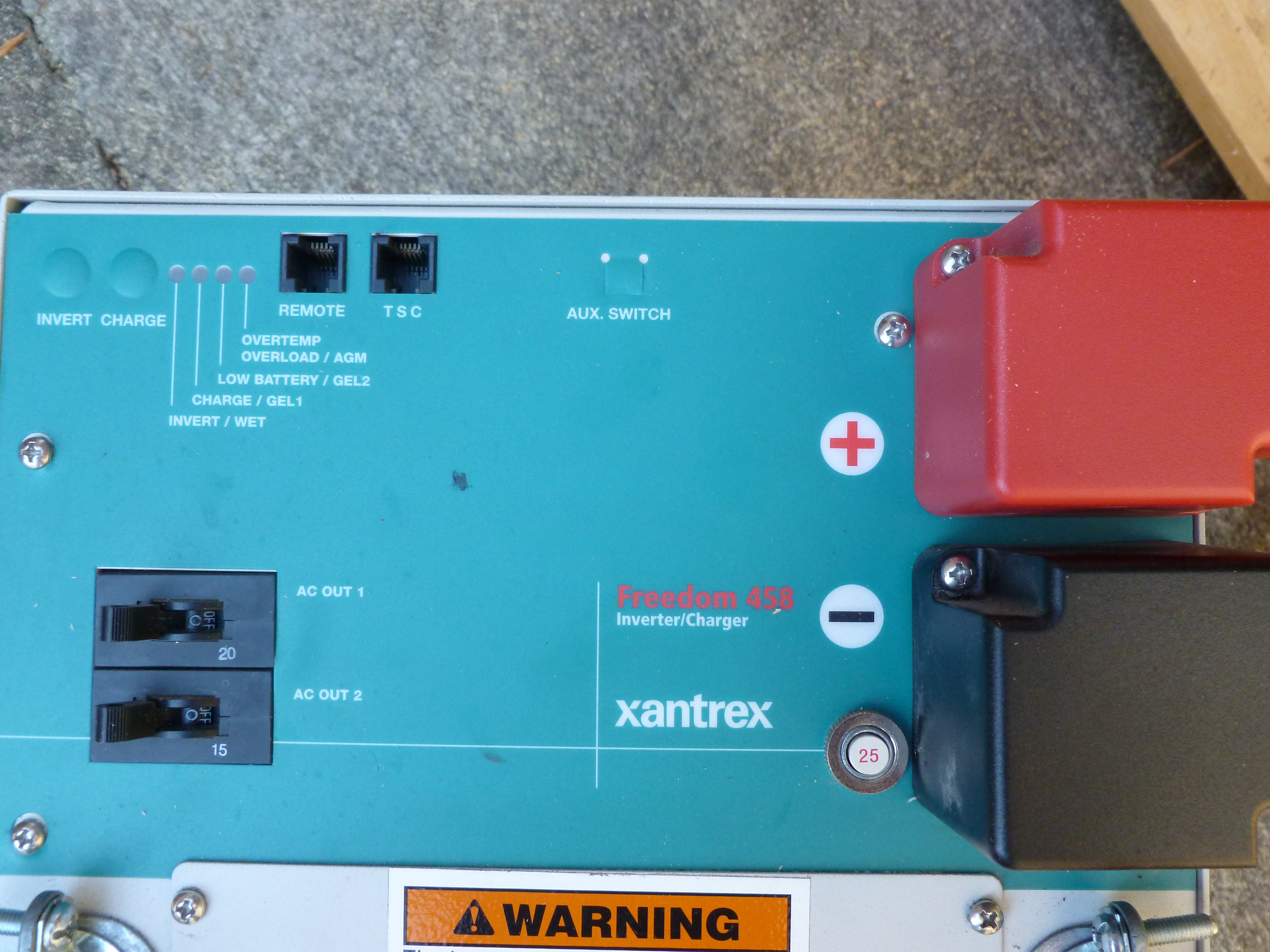
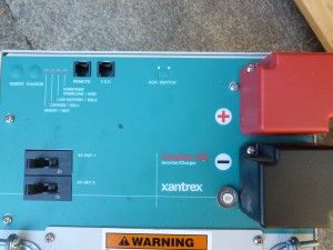
Of course, to run a 15 amp (120 volt) appliance off of a 12 volt supply you need something better than a $50 harbor freight inverter. Meet the Xantex Freedom 458, an inverter/charger originally designed for RV use. It provides dual 20 and 15 amp AC circuits plus a battery charger and AC pass-through from shore power when available. This means that it operates like a true UPS, running on grid current (shore power) and keeping the batteries charged when available, and immediately switching over to inverter power from the battery bank if the grid goes down.
I used AWG 2 gauge cables to connect the batteries to the inverter (because I couldn’t buy AWG 1 at Walmart) which should be good to at least 180 amps continuous (at 12 volts, this is the 2000 watt max rating of the inverter, well more than I plan on running through the system.)
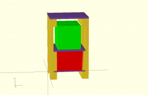
The most time consuming part of assembling the UPS was building an enclosure out of 2×4’s and plywood. (4x 28″, 4x 16″, 4x 9″, plus 2 shelves of 16×14.5″ and 1 top of 16×17.5″). I put the batteries on top under a removable top cover so that every few months I can unscrew a few wood screws, lift up the top, and easily water the batteries. If I expand the system to use more than 2 batteries I’ll probably invest in a tube based battery watering system.
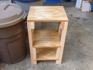
I also added casters to the bottom so that I can roll the UPS around to anywhere I want it (assuming it’s on the concrete garage floor, parking pad, driveway, or walkway).